
As you begin the transformation of your personal space into a modern smart home, a great starting point is to experiment with simple tasks. For instance, you could convert an old desk lamp into a smart light using just a few components:
- An old desk lamp
- A basic HW-622 Relay Module described here.
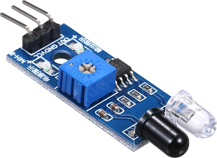
- A cheap obstacle sensor typically used in robotics
With these items, you can equip your old desk lamp with several smart capabilities:
- Remote control – via your smartphone (covered here)
- Vacation mode – a schedule for turning the lamp on and off, giving the impression that you’re home
- Auto off – an automatic shutdown after a pre-set amount of time, conserving energy
- Monitoring – data collection on light usage for further optimization of power consumption
Budget
| Item | Pcs | Unit price (€) |
| ayatec unicontrol mini | 1 | 4 |
| ESP8266 HW-622 Relay Module or similar | 1 | 3 – 7 |
| Infrared obstacle sensor module | 1 | 1 – 2 |
| 12V 1A Power supply | 1 | 3 – 6 |
| A scrap desk lamp | 1 | 0 |
Depending on your location and some luck with finding good deals, the cost of this upgrade could be as low as €14.
- A PIR motion sensor that turns the light on when someone enters the room,
- A capacitive touch sensor that toggles the light on or off upon touch,
- A vibration sensor that illuminates the light in response to mechanical disturbance (like a door knock),
- A photoresistor module that activates the light after sunset and deactivates it after sunrise, and more…
Smart Light Installation
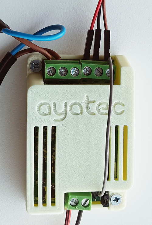
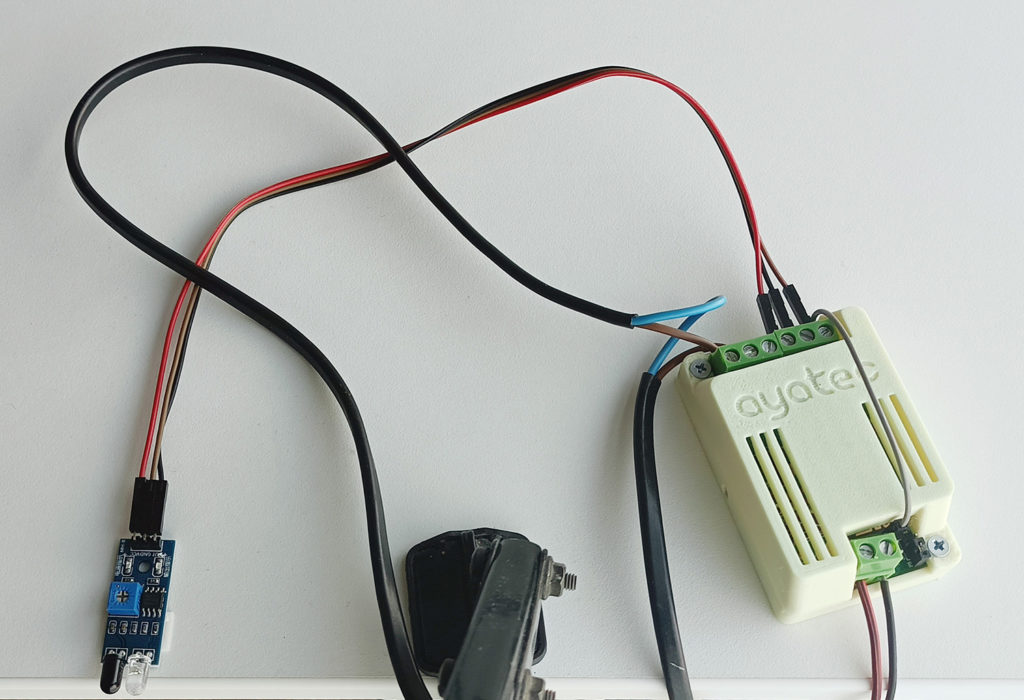
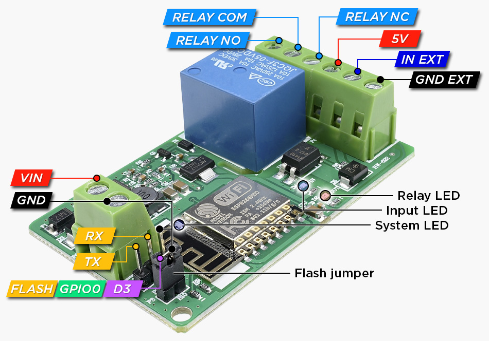
The physical installation of the system involves supplying power to the module and correctly connecting the sensor and lamp to their respective ports.
Power supply:
- Connect the adapter’s positive (+) terminal to the module’s
VINconnector (strong red cable) - Connect the adapter’s ground (-) terminal to the module’s
GNDconnector (strong black cable) - Interconnect the module’s
GNDandGND EXTconnectors. This avoids the need for an extra power supply for the sensor due to the optocoupler separation (grey cable) - Plug the adapter into the power socket
Sensor:
- First, connect the sensor’s
VCCpin to the module’s5Vconnector (red cable) - Second, connect the sensor’s
GNDpin to the module’sGND EXTconnector (grey/brown cable) - Finally, connect the sensor’s
OUTpin to the module’sIN EXTconnector (black cable)
Lamp:
Please be aware that the following steps involve working with 230V AC electricity. Ensure that you follow all relevant safety precautions, or consider having a professional handle the critical steps.
- Cut the lamp’s live line (L, brown wire) at a suitable location according to the final position of the module. Keep the neutral line (N, blue wire) intact.
- Strip both ends of the newly separated live line (L).
- Connect the two conductors to the module’s
RELAY COMandRELAY NOconnectors. Be careful not to use theRELAY NCconnector. - Plug the lamp’s adapter into the power socket
Smart Light Setup
Once power is supplied, the board can be flashed with the unicontrol software. For detailed instructions, you can refer to the introductory tutorial specifically written for this module. Afterward, follow the First boot tutorial to set up the Wi-Fi and establish a connection to the device.
Peripherals
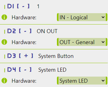
Once you’ve accessed the module via the Interface, navigate to the Peripheral menu and make sure that:
D1is set asLogical IND2is set asGeneral OUT
While not essential, it’s a good practice to maintain D3 as a System Button and D4 as a System LED.
Process
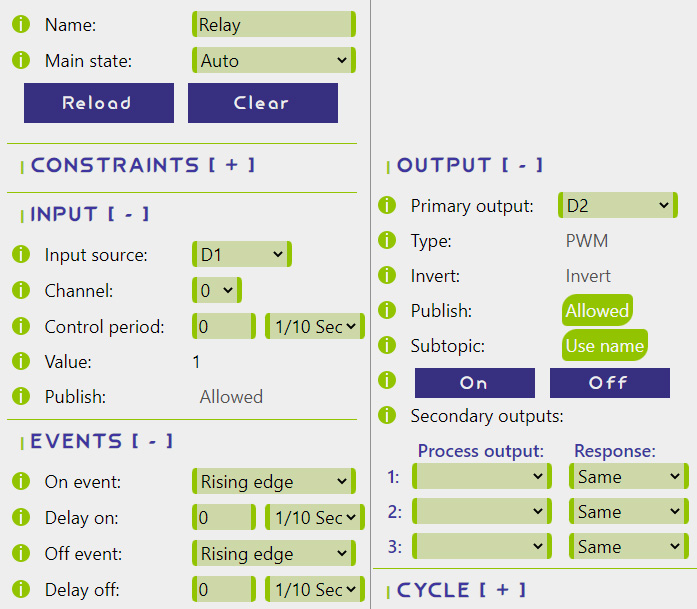
In the process set-up, you need to specify how the device’s relay (D2) will respond based on the input received (D1).
- First, assign a name to the process. While not essential for functionality, using intuitive and easily remembered process names simplifies MQTT setup.
- Set the Input source as
D1(sensor). - Set the Primary output as
D2(relay). - Set both On event and Off event as
Rising edge. This will sequentially turn the outputONandOFFwhen the sensor connected to theD1pin detects an obstacle. - Allow Publish. This will send an MQTT message every time the relay changes its state.
- Allow to
Use namein Subtopic. While not essential, this simplifies MQTT setup by including the process name in the MQTT topic for greater convenience. - Click “Save” to apply the changes.
Your module is now ready for operation.
Calibration and testing
After successful assembly and system setup, the sensor requires calibration using its built-in potentiometer to respond at the desired distance, which can be set anywhere between 2 and 30 centimeters. Moreover, it’s crucial to position the sensor correctly to avoid false triggers from the table itself or other objects within its range. Make sure to thoroughly test the new smart light to ensure that the sensor activates when it’s supposed to and remains inactive otherwise.
If you find that the sensor triggers too frequently or “eagerly,” you might want to consider setting a positive Control period.
MQTT setup
As usual, I will be using my preferred testing tools, the test.mosquitto.org broker and IoT MQTT Panel app, with the following placeholder settings in Wireless/MQTT menu:
- Connection:
Enabled - Broker:
test.mosquitto.org - Port:
1883 - User: empty
- Topic Level 1:
johndoe5896 - Topic Level 2:
home - Topic Level 3:
tablelight1
To gain initial control over the newly installed smart light, it’s enough to set up just a few simple panels (assuming the topic settings mentioned above):
- ON button – sends Payload
1to the Topicjohndoe5896/home/tablelight1/sub/Relay/outset - OFF button – sends Payload
0to the Topicjohndoe5896/home/tablelight1/sub/Relay/outset - Relay State LED – receives the current relay state from Topic
johndoe5896/home/tablelight1/pub/Relay/outputwith Payload0(relay off) or1(relay on) - Device State LED – receives the current device state from Topic
johndoe5896/home/tablelight1/pub/connwith Payload0(offline) or1(online) - Device IP address– receives the device’s current local network IP address as a Payload from Topic
johndoe5896/home/tablelight1/pub/ip
You may obtain further guidance you may follow this step-by-step tutorial to learn how to set-up the MQTT from scratch. Moreover, you can check the MQTT API documentation for a full technical reference.
Finalizations of the Smart Light
Once you’ve tested everything and confirmed that the installation is functioning as intended, the final step is to conceal the hardware, leaving only the lamp visible.
Were you successful in making your own smart light?
Ideas for further improvement
1
Several processes can be defined with both On and Off Force out, along with varying timers and days. This will make the light to turn ON and OFF in a quasi-random pattern, simulating your presence at home when you’re away.
2
You can also define a separate process to add an automatic Timeout to the lamp, causing it to turn off after a set period of time.
3
The relay state MQTT messages can be effectively used in NodeRED to monitor the lamp’s usage and calculate the associated power consumption. This same principle can be applied to transform the module into, for example, a universal counter.