Numerous third-party modules featuring the ESP8266 microcontroller are readily available in the market. Modules carrying the versions ESP-12E, ESP-12F, or ESP-12S are natively supported by unicontrol as they are equipped with 4MB Flash memory or more. They are typically less convenient when it comes to firmware uploads, compared to development boards like the WeMOS D1 mini or NodeMCU, they offer substantial flexibility regarding power supply and default hardware. A great example is the 4-channel X4 Relay Module.
The previously introduced HW-622 1-Channel Relay Module represented the most basic ESP8266-based hardware choice. Conversely, the X4 module (also known as ESP12F_Relay_X4) represents one of the most versatile options available.
Please note that modules utilizing ESP-01 or similar downsized versions of ESP8266 are not compatible due to their limited flash size. To ensure your board’s compatibility, please verify that it has a minimum of 4MB Flash memory.
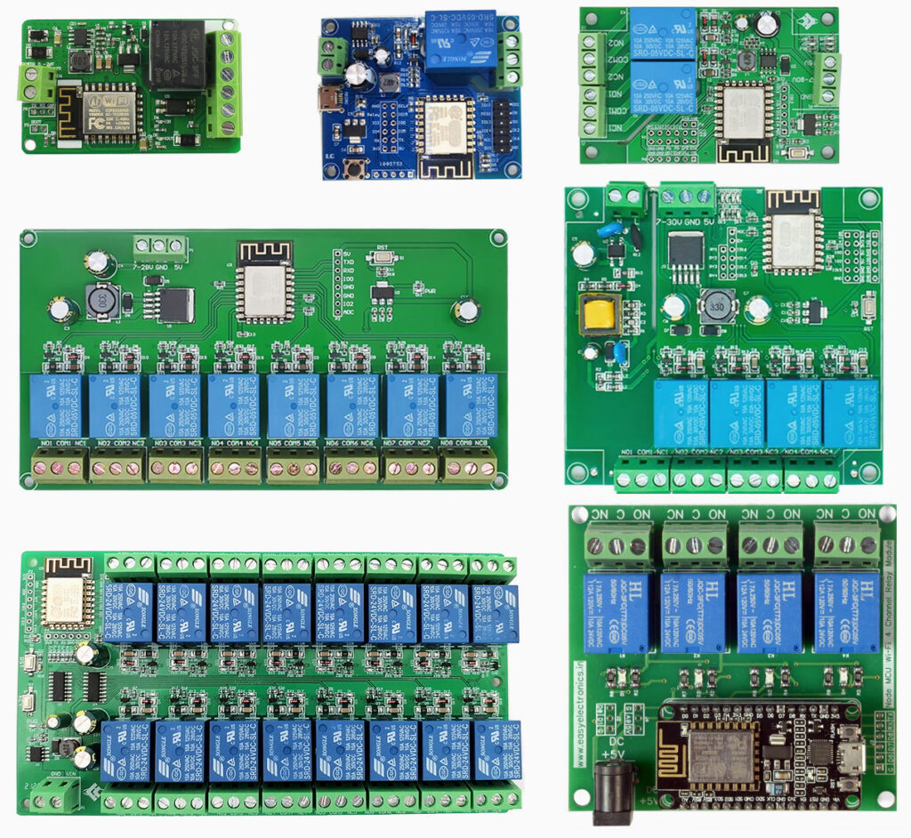
4-CHANNEL X4 RELAY MODULE
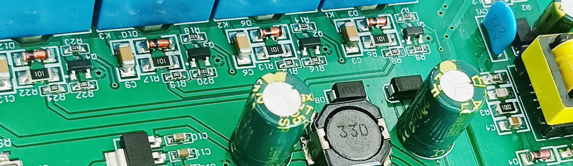
The Relay Module ESP12F X4 belongs to the most versatile ESP8266-based hardware with the following capabilities:
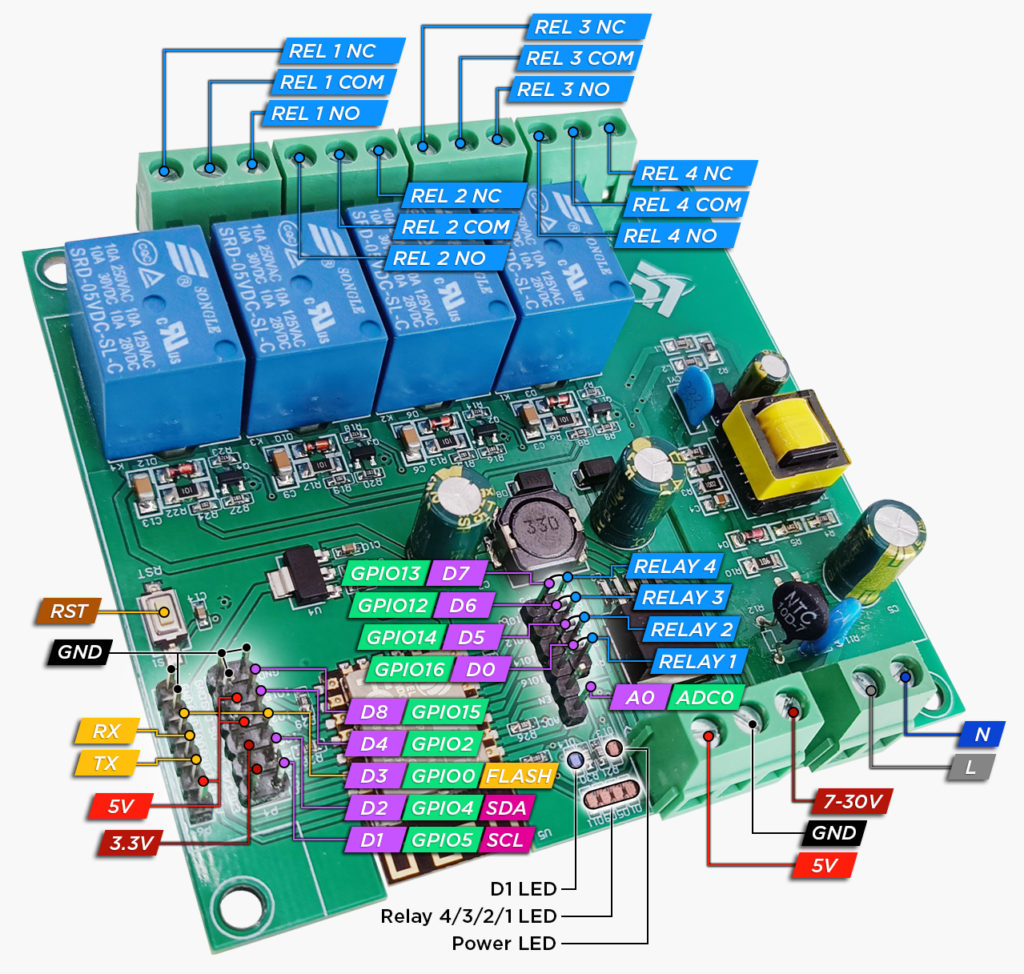
- 4 independent relay channels with a standard rating of
10Afor250V ACor30V DCon pinsD0,D5,D6, andD7. - The board contains a series of step-down convertors, which give three power supply options:
5V DC7-30V DC90-250V AC
- Indicator LEDs for the power supply,
D1pin, and all relays. - All ESP8266 GPIOs are accessible via PCB holes.
By default, this board expects you to use the D0, D5, D6, and D7 ESP8266 pins to control the relays using the provided jumpers. However, these assignments aren’t rigid. Feel free to connect the individual relays to any accessible digital pins from D0 to D8. You will be still left with six unused pins, which can be employed to enhance the board’s capabilities. You could add a standard 0.96″ TFT display or any standard input or special sensor, requiring only minimal additional assembly and wiring.
Although the X4 module can officially be powered by any voltage ranging from 7V to 30V, we do not recommend supplying more than 12V, as the generation of excessive waste heat may cause failure without the appropriate heat sink.
Flashing
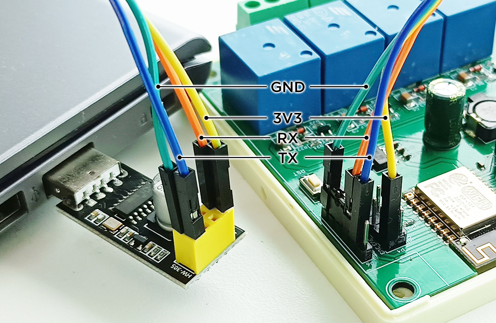
Similar to other comparable modules, the X4 does not include an on-board UART-USB converter, which makes firmware uploading less straightforward. To flash this board, follow these steps:
- Connect the UART-USB converter to the module by connecting the following pins:
TX -> TX,RX -> RX,GND -> GND, and3V3 -> 3V3(or5V -> 5V). (Please note that each UART-USB converter may have a different pin layout, so please refer to your own converter’s specifications. For more details on connecting the UART-USB converter to the ESP8266, refer to our Serial line tutorial.) - Use the included jumper or any cable to connect the module’s
IO0(D3) andGNDpins. This will initiate the Flashing mode upon the next reset. - Connect the power supply to the module (or press the RST button).
- Insert the UART-USB converter into your computer.
- Proceed to flash the device following the standard procedure outlined in our Flasher turorial.
- Disconnect the UART-USB converter from the module.
- Disconnect the module’s
IO0D3GNDpins to ensure a standard boot. - Reboot the module by pressing the RST button.
- Now you can proceed with the First boot tutorial.
Do not connect the 3V3 (or 5V) pin to the UART-USB converter during flashing if the module already has a separate power source to avoid possible hardware damage. Additionally, never interconnect the 3V3 and 5V pins, as doing so will cause immediate and permanent damage to the ESP8266.
ENCLOSURE
For a more convenient manipulation and installation of the X4 relay module you may print and use our own designed enclosure.
The case consists of two main components and optional DIN rail holders, which can be effortlessly assembled using standard M3x13 flat-head screws (or similar). This versatile case provides various installation options, including mounting on a DIN rail, attaching directly with screws, or fastening with zip-ties.
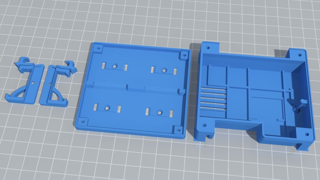
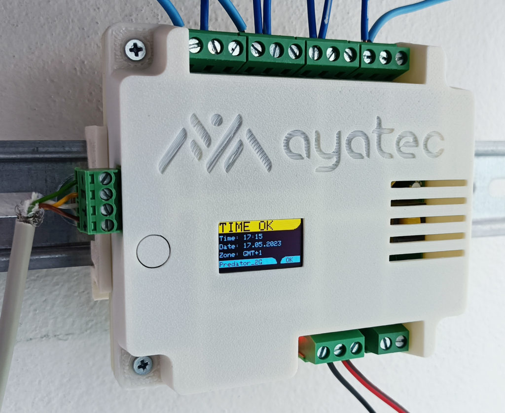
The model is equipped with a physical on-board RST button extension. Additionally, it features three optional pre-cut openings for the display and two connectors. Make sure to remove the relevant caps if you need the openings.
For maximum safety and durability, we recommend using ABS or ASA as the printing material.
Find more details on: