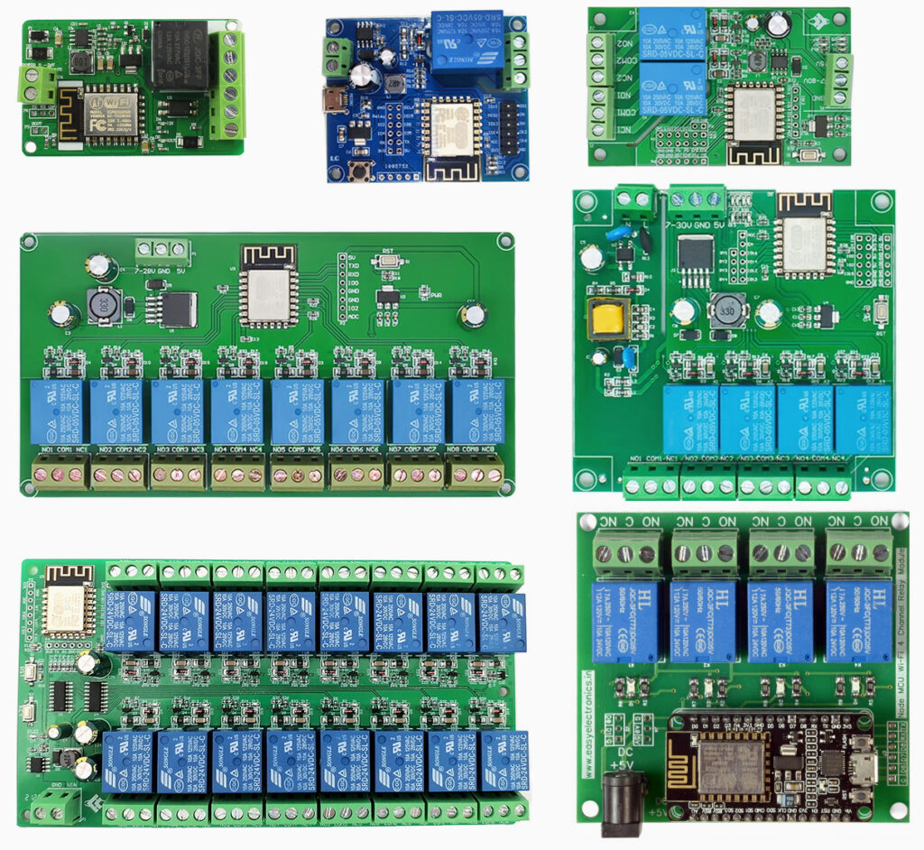
The majority of simple home projects do not require custom-made PCBs like the one demonstrated in the Bath Vent Project. Numerous ready-made modules featuring ESP8266 (or a socket for one) are available, most commonly integrating the ESP-12E or ESP-12F. These modules are natively supported by unicontrol, as they come equipped with 4MB Flash memory or more. Unlike development boards such as WeMOS D1 mini or NodeMCU, these modules typically lack a UART-USB converter. This makes firmware uploading significantly less convenient. On the other hand, they often provide more flexibility in terms of power supply options and available hardware. All without the need for additional assembly or accessories, with prices starting at around €5.
Please note that modules utilizing ESP-01 or similar downsized versions of ESP8266 are not supported due to their limited memory capacity. To ensure your board’s compatibility, please verify that it has a minimum of 4MB Flash memory.
HW-622 1-CHANNEL RELAY MODULE
The Relay Module HW-622, among those described above, is arguably the simplest option. It provides the following hardware features:
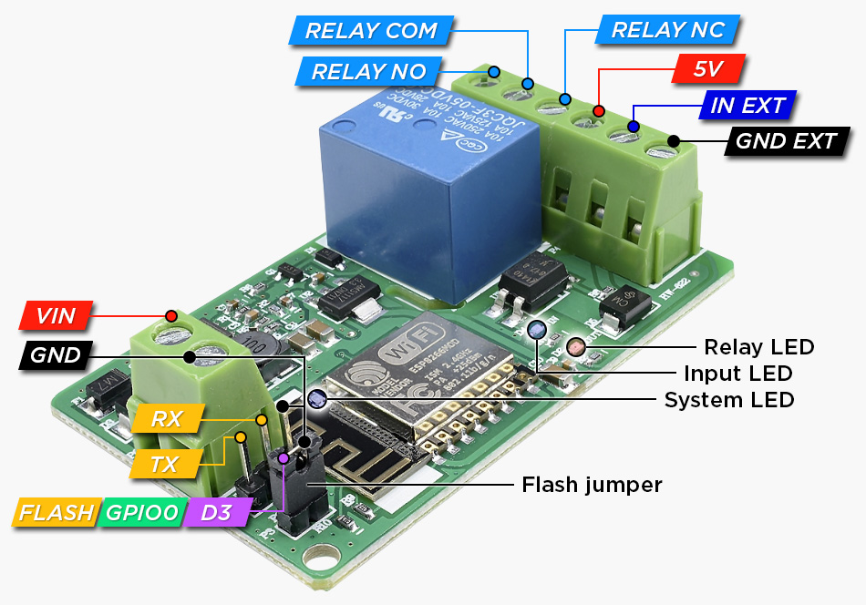
- A single relay output with a standard rating of 10A for 250V AC or 30V DC.
- A single optocoupler-separated logical input, which accepts only basic
TRUE/FALSEvalues. - Indicator LEDs on pins
D1(Input),D2(Relay), andD4(System). - Exposed
D3,GND,TX, andRXpins necessary for flashing.
Please note that the input and output are galvanically isolated from the board, enhancing safety when handling higher voltages on both sides. Consequently, the GND EXT is separate from the board’s GND. To use a sensor input on IN EXT, you have two options: either supply the sensor with an independent power source and connect its GND to the board’s GND EXT or connect the GND EXT to the GND and use the board’s 5V outlet to power the sensor.
Flashing
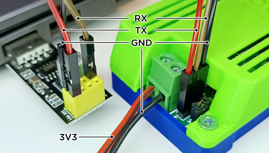
The HW-622 lacks a built-in UART-USB converter, making it less convenient for flashing compared to boards like the WeMOS D1 mini or NodeMCU. To flash the HW-622, follow these steps:
- Connect the UART-USB converter to the Relay module by connecting pins
TX -> TX,RX -> RXandGND -> GND. Be aware that each UART-USB converter may have a slightly different pin layout, so please refer to the specifications for your specific converter. For more details on connecting the UART-USB converter to the Relay module, refer to our Serial line tutorial. - Connect the module’s
D3andGNDpins using the included jumper or any cable to switch the device into Flashing mode. - Connect the power supply to the Relay module.
- Insert the UART-USB converter into your computer.
- Flash the device using the standard procedure described in the Flasher turorial.
- Disconnect the UART-USB converter from the Relay module.
- Disconnect the Relay module’s
D3andGNDpins to ensure standard boot upon the next reboot. - Reboot the module by disconnecting and reconnecting the power supply.
- You may now follow the First boot tutorial.
The HW-622 module is unique in comparison to the modules mentioned above, as it does not have any exposed 3.3V or 5V pins usable for flashing. Unlike most other modules that can tap the UART-USB converter for power during the flashing process, the HW-622 requires its own independent power supply throughout the entire process.
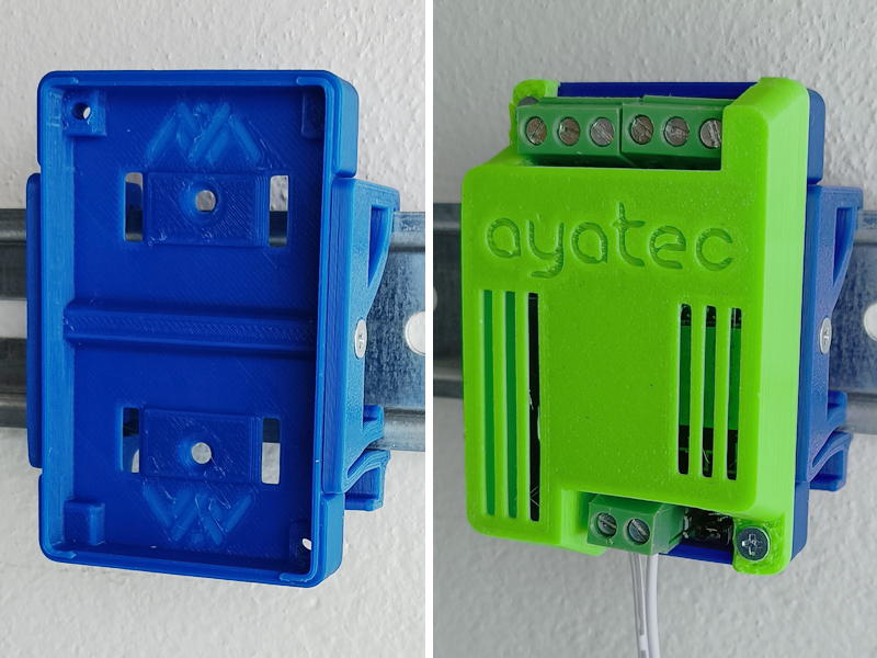
ENCLOSURE
For a more convenient manipulation and installation of the HW-622 module you may print your own designed enclosure.
The case consists of two main components and optional DIN rail holders, which can be effortlessly assembled using standard M3x13 flat-head screws (or similar). This versatile case provides various installation options, including mounting on a DIN rail, attaching directly with screws, or fastening with zip-ties.
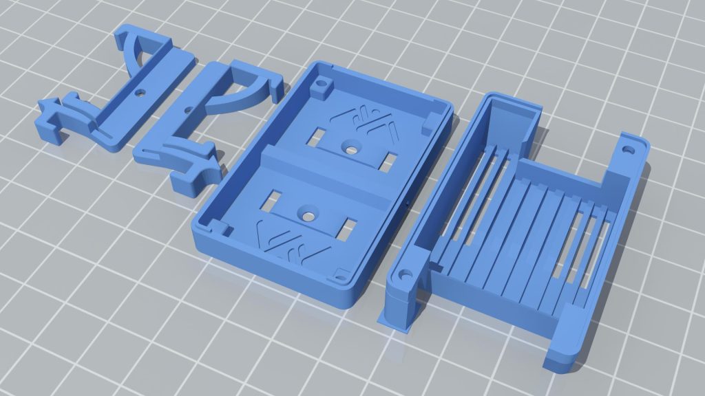
For maximum safety and durability, it is recommended to use ABS or ASA as the printing material.
Find more details on:
TIPS AND TRICKS
1
While the D3 pin is primarily for flashing purposes and lacks a convenient on-board connector, it is fully available for use as an extra input or output. Unlike D1, this pin is not connected through an optocoupler, so it retains its full functionality, including PWM output or temperature reading capabilities.
2
The board’s internal 5V power supply appears to have a pronounced sine-phase, which may cause induction and interfere with the connected sensor. Implementing a drop voltage regulator, such as the LD1117, can help resolve this issue by converting the HW-622‘s internal 5V supply into a less interfering 3.3V supply.
3
Although the HW-622 can officially be powered by any voltage ranging from 7V to 30V, we do not recommend supplying anything above 12V, as the generation of excessive waste heat may cause failure without the appropriate heat sink.