
Introduction
Water is a precious resource, and with climate change and population growth, it’s becoming increasingly important to monitor and manage our water usage. Picture this: It’s an early Tuesday morning, and the day’s tasks are already running through your mind. As part of your routine, you turn on the shower, letting the water flow freely as it warms up. You’re not in the shower yet, but the water is already rushing down the drain.
Suddenly, your phone buzzes with a notification. It’s from your home’s water monitoring system, alerting you to the amount of water your shower is consuming. The numbers are higher than you expected – the water you’ve wasted just waiting for the right temperature could fill a whole swimming pool over a year! You realize that by simply adjusting your routine – turning on the shower only when you’re ready to step in – you could save a significant amount of water. It’s a small change, but one that could lead to substantial water and energy savings over time.
This is the power of real-time data. It’s not just about numbers and graphs; it’s about understanding our habits and making informed decisions for a more sustainable future. And in this project, we’ll show you how to set up your own water monitoring system to start making these changes today.
In this project, we will show you how to create a live graph using MQTT mobile app of your cold and hot water usage along with their respective temperatures, using ESP8266 minicomputer, water flow sensors, and temperature sensors. Not only will you be able to keep track of your water consumption, but you’ll also gain valuable insights into your home’s water temperature trends, which can lead to improved energy efficiency and cost savings.
Before we dive into the specifics, let us briefly discuss the benefits of this project:
Now we can dive deeper into the details of building and setting up your own water monitoring system. We’ve outlined a comprehensive structure to ensure you have a smooth and enjoyable experience as you embark on this exciting smart home project.
Choosing Your Assembly Path: 3 Options to Suit Your Needs
We understand that every DIY enthusiast has different skill levels and budget constraints. That’s why we’re offering 3 different options for assembling your very own water monitoring system. Choose the option that best suits your needs and abilities, and let’s get started on creating a smarter, more efficient water management system for your home.
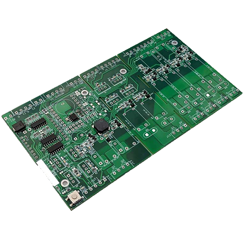
Option 1: DIY from Scratch (Most time-intensive, but the cheapest) (RECOMENDED)
While this option may initially appear to be the most challenging, rest assured that it’s entirely manageable with our comprehensive guide. The assembly of the system requires minimal tools, and we’ve broken down each step for your convenience. Here’s your roadmap to creating your own water monitoring system:
- Download the fabrication data for the printed circuit board (PCB).
- By following our guide for using JLCPCB to produce your PCB, you can obtain a nearly finished product at an extremely good price. While you’re free to use other facilities for your PCB production, we cannot guarantee as smooth an assembly process as with JLCPCB. Our guide has been specifically tailored to their services for optimal results.
- Purchase the required ESP8266 board, parts and sensors.
- Follow our step-by-step guide to assemble the components and connect the sensors.
- Install our dedicated software onto the ESP8266 board, then configure the settings based on our guide.
- Visualize the data using Node-RED or any MQTT app. This provides seamless data representation and analysis, and we provide a guide to help you through this process.
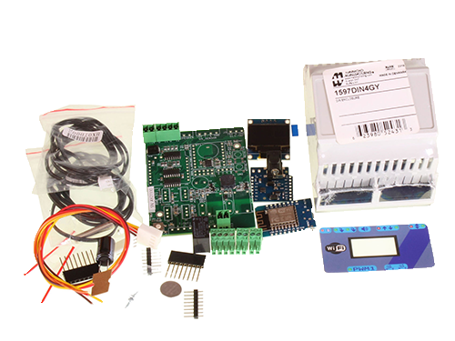
Option 2: Partially Assembled Kit (Moderately priced, some assembly required)
If you prefer a slightly easier route and are willing to spend a bit more, we offer a kit that includes a pre-assembled PCB with the required components. With this option, you’ll need to:
- Purchase the partially assembled kit from our e-shop, which includes the almost ready-to-use PCB and the compoentns.
- Assemble the PCB with the parts from the kit.
- Follow our step-by-step guide to connect the sensors to the PCB.
- Install our software onto the ESP8266 board and configure the settings according to our guide.
- Visualize the data using Node-RED or any MQTT app. This provides seamless data representation and analysis, and we provide a guide to help you through this process.
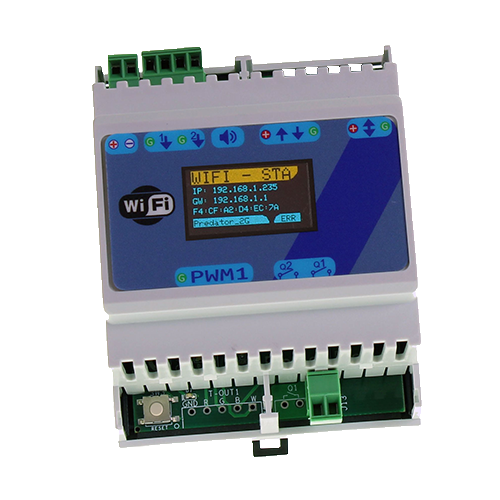
Option 3: Ready-to-Use Package (The quickest setup, but the most expensive)
For those who want a hassle-free experience and are willing to invest in a complete, ready-to-use system, we offer a fully assembled package. All you need to do is:
- Purchase the ready-to-use package from our e-shop, which includes the fully assembled PCB with ESP8266 board, and sensors.
- Follow our simple guide to set up the sensors in the desired locations.
- Visualize the data using Node-RED or any MQTT. This provides seamless data representation and analysis, and we provide a guide to help you through this process.

We hope these options help you choose the best method for creating your own water monitoring system. While we recommend Option 1 — which, despite appearing a bit complex, is not complicated — we believe the cost-effectiveness and potential for learning new skills make it a worthwhile venture. Regardless of the option you choose option you select, our comprehensive guide will be there to support you through every step of the process.
Precautions and Tips
To ensure your safety and successful implementation of your home water monitoring system, follow these precautions and tips:
- Safety first: Always disconnect power when working with electronic components, wiring, or making adjustments to your system. This will minimize the risk of electrical shocks or damage to your components.
- Check connections: Double-check all wiring connections and ensure they are secure and correctly placed. Loose or incorrect connections can result in inaccurate readings or even damage to your components.
- Workspace organization: Before starting the assembly, organize your workspace to minimize the risk of losing or misplacing components. Having a clean and well-lit work area can also reduce the likelihood of errors.
- Follow a step-by-step approach: Assemble your system in a logical sequence, following the provided instructions or schematics closely. This will help you avoid confusion and ensure that all components are connected correctly.
- Avoid excessive force: When inserting components into a breadboard or PCB, use gentle pressure to avoid bending pins or damaging the board. Excessive force can result in permanent damage to components or connections.
By following these precautions and tips, you can avoid common mistakes and ensure the safe, smooth, and accurate operation of your water monitoring system.
Navigate to Your Chosen Assembly Option
Once you’ve selected the option that best suits your needs, we’ve made it easy for you to jump directly to the related section of our step-by-step guide. Simply click the button corresponding to your chosen assembly option, and you’ll be taken to the relevant instructions to help you complete your project with ease. Also below you can find a list of parts with link that you’ll need for Option 1:
| Parts | Price Per Piece (≈) |
| 1x ESP8266 Board | 2,00€ |
| 1x Power Shield | 0,80€ |
| 1x Power Adapter | 2,00€ |
| 1x Condensator | 1.80€ |
| 2x Temperature Sensor (DS18B20) | 1,20€ |
| 1x OLED Display (Optional) | 2,00€ |
| 2x Relay (Optional) | 1.20€ |
Choosing the right water flow sensor is a crucial step in setting up your water monitoring system. Here are some factors to consider when selecting a sensor :
- Flow Rate: The flow rate is the quantity of water that passes through the sensor per unit of time. It’s important to choose a sensor that can accurately measure the flow rate in your household. For most homes, a sensor that can measure up to 30 liters per minute should suffice.
- Durability: The sensor will be in constant contact with water, so it needs to be durable and resistant to corrosion. Sensors made from materials like brass or stainless steel are typically a good choice.
- Fitting: This depends mainly on your piping design. But you can choose your sensor based on one of these two measurements :
- DN: DN stands for “Diamètre Nominal” which is a French term that translates to “Nominal Diameter”. It’s a European designation used to indicate the size of the pipe that the sensor (or any other fitting) is designed to fit. For example, DN20 means the sensor is designed to fit a pipe with a nominal diameter of 20 millimeters.
- G: The “G” in G1/2 stands for “Gas” and is a standard for pipe thread, which is a system used for fitting pipes together. The number following the “G” (in this case, 1/2) refers to the nominal inside diameter of the pipe in inches. So, G1/2 means the sensor is designed to fit a pipe with a nominal inside diameter of 1/2 inch.
Now, if you are asking if it’s possible to fit a larger sensor on a smaller pipe, yes, it is possible to use a reducer to fit a larger sensor to a smaller pipe. A reducer is a fitting that connects two pipes of different diameters. However, there are a few things to consider: Accuracy, Pressure Loss, Installation Complexity. So, while it’s possible to use a reducer, it’s generally best to choose a sensor that matches the size of your pipes.
In the United States, the most common diameters for supply pipes are 1/2 inch and 3/4 inch. In many European countries, the equivalent sizes in millimeters are typically 15mm and 22mm.
Ordering Your Custom PCBs
We’re here to walk you through ordering your very own custom circuit boards. Now, JLCPCB requires that you order at least five boards at a time. But don’t worry, this option should still be cheaper than buying a ready-to-build package or a pre-made product. Plus, we think this is a great deal! Why? Because we’ve got lots of awesome DIY projects that all use the same board. So, by grabbing this bargain, you’re all set to make loads of projects that will help you turn your home into a smart haven. Curious about these projects? You can check them out right here:
- Download the provided .zip (fabrication-data) file.
- While we recommend JLCPCB for printing boards, feel free to choose any manufacturer that suits your needs.
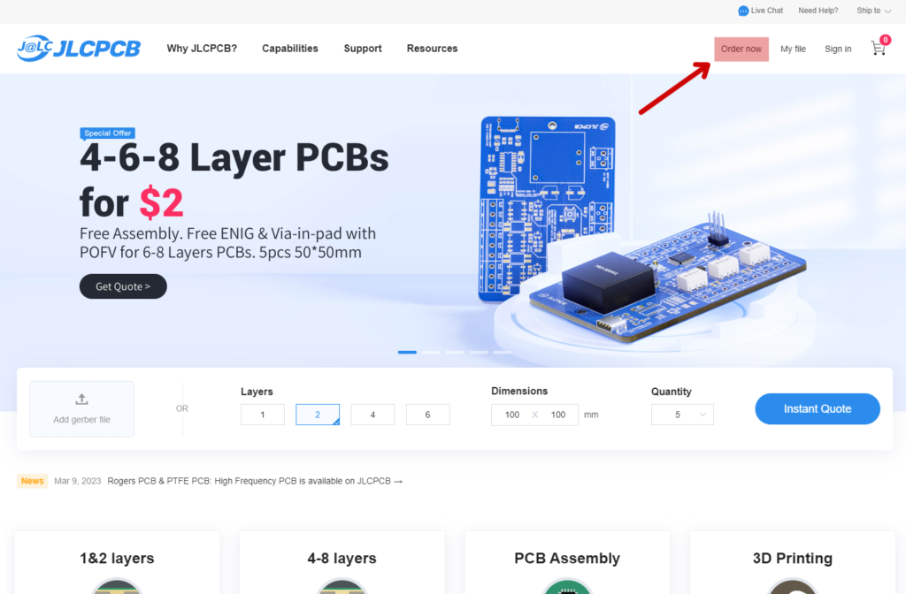
- Navigate to JLCPCB.com, and click on “Order Now” in the top-right corner.
- Upload the .zip file containing the Gerber file. There is no need to extract the file before uploading.
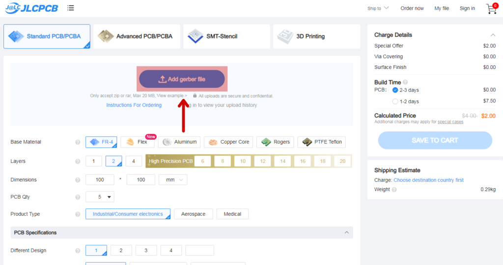
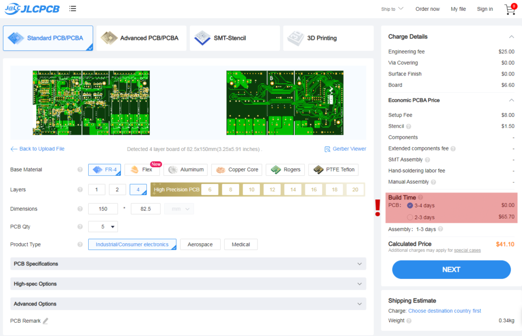
- Upon successful upload, you should see a preview of your board.
- NOTE: The build time displayed on the right side of the page can significantly impact the price. Opting for a faster build time may only shorten the process by one or two days, while substantially increasing the cost.
- If you prefer to have the components assembled by the manufacturer, select the “PCB Assembly” option at the bottom of the page. We recommend this choice for those without the necessary skills or experience in assembly.
- Complete your order and await the delivery of your custom PCBs.

After getting your PCB you can solder the last required parts based on the schematic provided below :
Preparing Your Sensors and Components for Installation
Before you begin, ensure that you have the assembled PCB (Printed Circuit Board) ready. The following steps will guide you through the process of connecting all necessary components. We have included images for each step to facilitate a smooth experience.

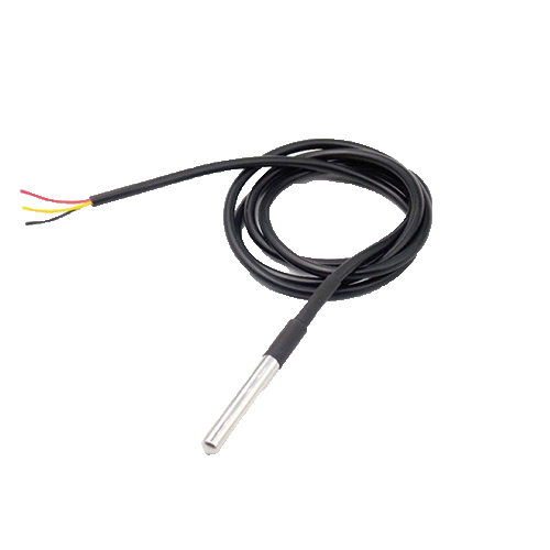

- Prepare the sensors you plan to connect to the system.
- If the copper cables are not exposed, strip the insulation using a knife, as demonstrated in the image below.
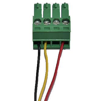
- Identify the plugs that correspond to the PCB and connect the cables according to the guide below.
- Connect your temperature sensors to the plug as shown in the images.
- NOTE: Our system supports multiple temperature sensors connected to a single plug and differentiates between their channels. However, it can only accommodate two water flow sensors. Refer to the images provided for guidance.


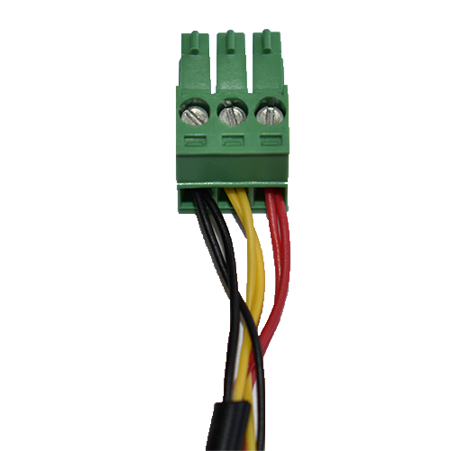
- Connect your water flow sensors to the plug as displayed in the images.
- Prepare the power adapter by connecting a 12V adapter to the appropriate plug.
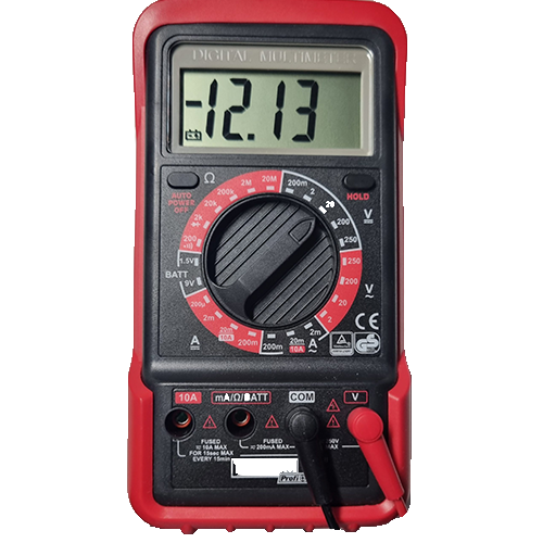
- NOTE: If you are uncertain which cable is positive and which is ground, use a multimeter to determine the correct configuration. A negative reading (-12V) on the multimeter indicates that the cables are reversed.
- WARNING: Exercise caution during this step, as the adapter must be plugged into an electrical outlet to obtain an accurate reading. The wires will be live, so handle them carefully.

Configuring the Software for Your System
Congratulations on reaching the software configuration stage of your project! If you have already prepared the software, you can proceed with the configuration process. If you have not yet set up your ESP8266 board, please refer to our First Boot guide for detailed instructions on installation and initial setup. Once completed, follow the steps below to configure your device for accurate data reading from the connected sensors.
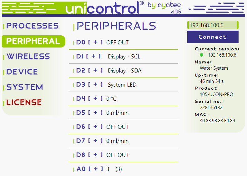
- After connecting to the ESP8266 board using our software you want to open the peripheral tab.
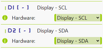
- If you are using a display, set the
D1pin to “Display – SCL” and theD2pin to “Display – SDA“.
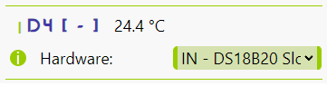
- Configure the temperature sensors by setting the
D4pin to either “IN – DS18B20 Slow” (reads input every 10 minutes) or “IN – DS18B20 Fast” (reads input every 5 seconds). We recommend using the fast setting.
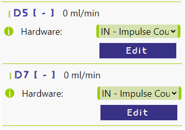
- Set up the water flow sensors by assigning the
D5pin to “IN – Impulse Counter“. If you are using two sensors, do the same for theD7pin.
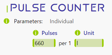
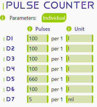
- To obtain accurate readings from the water flow sensors, check the pulse rate per ml/L for your specific sensors. If your sensors have different pulse rates, click the “Individual” button and set the correct parameters for the
D5andD7pins. Otherwise, simply set the pulses per unit.
- At this point, the “Peripherals” tab should look like the image.
- Next, navigate to the “Processes” tab to set up each process for reading and sending data to Node-RED for visualization.
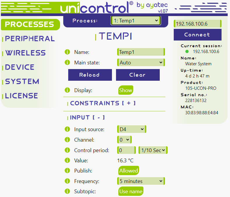
- Configure your temperature sensors acording to the setup below.
Process_1 : Temp1
- Main state ->
Auto - Input source ->
D4 - Channel ->
0 - Enable Publish and Subtopic
- Frequency – You can choose the desired frequency but we recommend 5 minutes.
Process_2 : Temp2
- Main state ->
Auto - Input source ->
D4 - Channel ->
0 - Enable Publish and Subtopic
- Frequency – You can choose the desired frequency but we recommend 5 minutes.
- NOTE: The images provided below may depict some tabs or options as closed for simplicity and clarity. Your interface may display additional options.

- Next, configure the water flow sensors as described below.
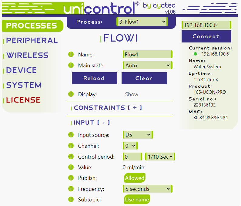
Process_3 : Flow1
- Main state ->
Auto - Input source ->
D5 - Enable Publish and Subtopic
- Frequency -> you can choose the desired frequency for sending readings but we recommend 5 seconds
Process_4 : Flow2
- Main state -> Auto
- Input source ->
D7 - Enable Publish and Subtopic
- Frequency -> you can choose the desired frequency for sending readings to Node-RED but we recommend 5 seconds

- Now, all sensors should be correctly configured. To test them, connect the sensors to the PCB and review the “Value” section under the “Input” tab for each process. To test the water flow sensor, blow gently into it for a few seconds, ensuring the correct orientation according to the arrow on the sensor.
Installing Sensors for Optimal Monitoring
The process of installing and configuring sensors may vary depending on your specific circumstances, such as differences in pipe systems or available installation space. While creating a step-by-step guide for every possible scenario is challenging, we can offer general guidance to help you achieve the best possible setup for accurate monitoring.
You’ll need to plug your system into a power socket. If there’s one near your pipes, perfect! If not, and you’re thinking about installing a new one, make sure you know what you’re doing. If not, it might be a good idea to get someone who knows about this stuff to help.
Please follow this general guide that should work for most pipe materials:
- Clean the pipe surface: Before attaching the sensors, make sure the pipe surfaces are clean and free of dirt, grease, or any other substances that may prevent good contact between the temperature sensors and the pipes. You can use a cloth and rubbing alcohol to clean the surface.
- Attach the water flow sensors: For most types of pipes, you’ll need to cut the pipe and insert the flow sensors in line with the water flow. Ensure that the flow direction arrow on the sensors matches the direction of water flow. Use appropriate fittings or adapters to connect the flow sensors to the pipes, ensuring a leak-proof connection. For metal pipes, you may need to use Teflon tape on the threads to ensure a proper seal.
- NOTE: When you’re installing the water flow sensor, it’s a good idea to use a silicone seal instead of a plastic one. The plastic ones can work, but we recommend silicone ones .
- Attach the Dallas temperature sensors: Depending on the pipe material, choose one of the following methods to attach the temperature sensors:
- For metal pipes:
- Use thermal paste or a thermal pad to ensure good thermal conductivity between the sensor and the pipe.
- Secure the sensor onto the pipe using a cable tie or metal hose clamp. Make sure the sensor is in full contact with the pipe surface.
- For PVC or plastic pipes:
- Use a small piece of self-adhesive aluminum tape on the pipe where the sensor will be placed. This will help improve thermal conductivity.
- Place the sensor on the aluminum tape and secure it with a cable tie or if your pipes are insulated you can instert it under the insulation.
- For insulated pipes:
- Cut a small section of insulation to expose the pipe surface.
- Attach the sensor using the appropriate method for the pipe material (as described above).
- Replace the insulation around the sensor and secure it with tape or a cable tie.
After attaching the sensors, make sure that all connections are secure and leak-free. Then, you can proceed with connecting the sensors to the PCB and running your water monitoring system.
Data Visualization: Insights into Your Water Usage
In this section, we will guide you through the process of setting up MQTT app to communicate with your monitoring system. By establishing this connection, you can efficiently visualize and analyze your water usage data for better understanding and management.
When it comes to data visualization, you have two primary options:
- Hosting Your Own Broker: This approach offers a broad spectrum of possibilities. You could set up a microcomputer, such as a
Raspberry Pi, connected to your local area network, or you could reserve capacity on a professional online server. - Using an External Service: There is a vast array of ready-to-use online MQTT brokers to choose from. These range from free services suitable for personal use to industrial-grade services designed for large-scale, professional applications.
While we won’t be detailing the process of hosting your own broker in this guide, we’d be more than willing to create a comprehensive guide on the subject if there’s sufficient interest. For now, let’s focus on using an external service.
- NOTE: One downside to using an external service is that if you wish to maintain a history of readings, a database setup is necessary. This is because most, if not all, apps don’t store the data.
- To set up MQTT in our software navigate to MQTT Settings, you’re free to choose your own naming system. However, if you opt to use ‘test.mosquitto.org’ (IPV4: 91.121.93.94) as your broker, ensure that you avoid generic topic level names. If your topic names coincide with those used by others, your setup won’t function correctly.
- NOTE: When configuring your settings, leave the user and password fields empty. Mosquitto accepts only anonymous MQTT messages.
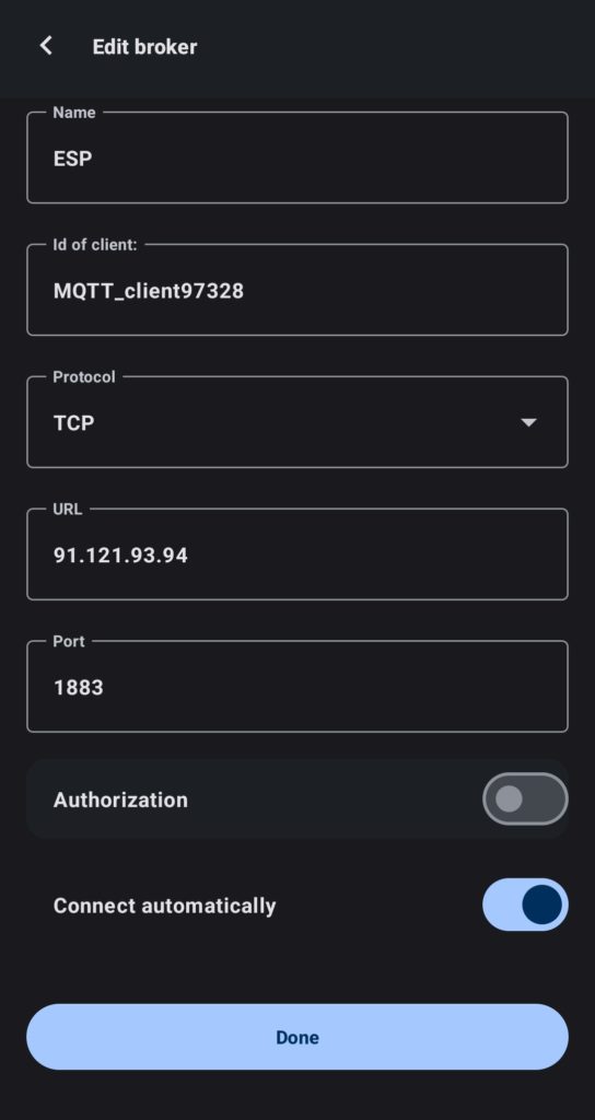
- The next step involves downloading an app, such as MQTT Client. After installation, select ‘add broker’ and set up the IP address and port according to your setup in our software.

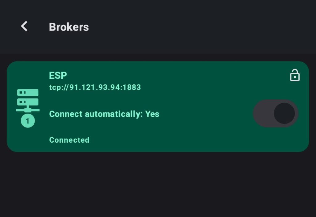
- Upon successful connection, you should see a green box showing connected as on the image provided.
- Now, you want to create a group and then a widget. Here is the configuration for reference:
- NOTE: In the Topic setting, align it with your naming. If you’re uncertain about the MQTT Topic naming, it can be found in our software under the INFO button of Publish.
- By clicking on the widget, you should now be able to see a graph representing your water usage. By following the same steps, you can add all other readings into your app.
- NOTE: If your readings are in units that are difficult to interpret (for example, milliliters), you can adjust the measurements using our software. Connect to your board, navigate to Peripherals, then click on
D5orD7. Select Edit, and here you can set up measurements in liters. For instance, if one impulse corresponds to one milliliter, you can set up the system to represent 1000 impulses as 1 liter.


So, this was the last step of our guide. If you’ve made it this far, congratulations! Now that you’ve seen the potential of our DIY water monitoring system, it’s time to take action. Start building your own system today and become a part of the solution to our global water and energy challenges. Share your progress, experiences, and any innovative modifications you make to the system with our community. We can’t wait to see how you contribute to a more sustainable future. Remember, every drop of water saved counts, and your journey towards water conservation starts here.
Conclusion
By following this blog, you now have the necessary knowledge to build and implement your own water monitoring system in your home. This project will help you better understand your water consumption habits and make more informed decisions about energy usage. We hope you find this system beneficial in creating a more sustainable and efficient living environment. If you have any questions about this project or a problem you can post a comment and we will make sure to help you. Happy tinkering!