
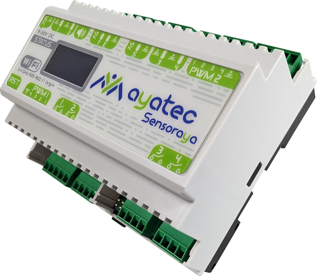
To unlock the full potential of the ESP32-S3, we developed the next generation of our programmable I/O boards. The ayatec sensoraya v2 bridges the gap between silicon and the physical world by significantly expanding the already powerful ESP32-S3‘s native I/O capabilities. This allows the sensoraya v2 to serve as a robust foundation for everything from smart-home nodes to specialized industrial automation systems.
Our hardware and software are built for deep customization. This synergy allows developers to scale effortlessly from simple, compact logic to complex, high-reliability embedded applications.

1. PCB Changes and Uses
The sensoraya v2.1 represents a significant architectural leap over its ESP8266-based predecessors. Built around the powerful ESP32-S3-WROOM-1U, the new revision integrates a W5500 Ethernet module and external antenna connector for high-reliability networking, built-in optocouplers for robust industrial interfacing, or an on-board USB-C port for easy communication with the chip.
We have eliminated previous hardware trade-offs to provide maximum variability while retaining the classic Hammond enclosure, refined with a more contemporary aesthetic. The result is a professional-grade controller ready for a wide range of applications, including:
- an autonomous, or remotely controlled smart relay box,
- an autonomous irrigation system,
- an aquarium or a swimming pool controller,
- a sauna or spa control including attractions,
- an indoor or outdoor LED lighting control,
- a remote gate control,
- a tank water level monitoring system with autofill,
- an autonomous thermostat or A/C,
- a temperature or air quality monitor,
- and a lot more!
2. PCB Sizes
The sensoraya features a segmented PCB design (Segments A, B, and C), allowing the board to be scaled physically based on the project’s I/O requirements. As the core segment A is fully autonomous, segments B and C can be removed to create three distinct size variants.
The I/O diagrams and descriptions provided in the following sections relate to the maximum configuration of the sensoraya PCB.
For the comprehensive listing of hardware capabilities of all the size variants you may check the following overview (sizes expressed in standard DIN modules):

Mini variant
(4-module)

The board’s core contains the ESP32-S3 microcontroller with the 7-30V VIN adapter and:
- 2 Relays
- 4 Power MOSFETs
- 5 Direct GPIO digital inputs
- I2C dedicated display connector
- DFPlayer MP3 module
- RTC module
- W5500 Ethernet module
- WiFi Antenna connector (integrated within the chip)
Mini variant is the smallest option (only 7 cm wide), best for compact applications requiring only a limited number of inputs and outputs.

Medium variant
(6-module)

Contains all options from the Mini variant with the addition of:
- 2 Relays
- 5 Optocoupler inputs
- 4 Power MOSFETs
- On-board Buzzer
Medium variant is the middle option (10,5 cm wide), providing additional inputs and outputs and representing the “sweet spot” for many automation projects.

Maxi variant
(9-module)

Contains all options from the Medium variant with the addition of:
- 6 Relays
- 8 Analog inputs
Maxi variant is the most powerful and largest option (16 cm wide). Designed for complex industrial logic or full-scale automation hubs requiring extensive sensing options and high relay counts.

3. PCB I/O description
The sensoraya v2 eliminates the hardware trade-offs of previous generations with all hardware capabilities being available simultaneously. While some solder jumpers remain present, they are used exclusively for fine-tuning the electrical behavior of GPIO and PWM outlets rather than selecting between mutually exclusive features (please refer to the schematic for more details).
The board transforms the ESP32-S3‘s native processing power into a following I/O array:
Output capabilities:
- 10 relays (4x 8A @ 250V AC (Changeover/SPDT) + 6x 5A @ 250V AC (Standard/SPST))
- 8 power MOSFETs (max 2.5A per channel @ 30V DC without external cooling)
- Audio/Visual: Buzzer and a dedicated MP3 module (DFPlayer) for alerts, sound effects, or music
Input & Connectivity:
- 5 optocoupler inputs
- 8 analog inputs (10kΩ)
- 5 direct GPIO digital/touch/analog multipurpose pins (ideal for digital peripherals like DS18B20, 1838 IR, HC-SR04, and other)
- Communication: W5500 Ethernet port, WiFi antenna, I2C dedicated connector (primarily intended for display), RTC module
The board requires a power supply of 7-30V DC via a dedicated connector in the upper-left corner of the board. Make sure that your power supply is capable of providing at least 10W.

Navigate to the official schematic for more detailed sensoraya v2.1 technical reference.
4. Relay Outputs
As the most basic output, the sensoraya PCB features up to 10 medium-load power relays of the following two types:
- Standard/SPST relay with maximum load of 5A @ 230V (up to 6 units in total, 2 units located on each of the segments A, B, and C)
- Changeover/SPDT relay with maximum load of 8A @ 230V (up to 4 units in total, all located on segment C)
The on-board relays can only be accessed in combination with the board’s built-in 74HC595 Shift Register and its output pins RE1 – RE10 (please refer to the schematic for more details).
Each relay has a dedicated on-board indicator LED showing the current output state of the respective relay.
Connectors J9 – J14 and J16 are dedicated to the power relays. Standard two-terminal relays share the 4-pin connectors in pairs, while each three-terminal changeover relay has its own 3-pin connector.

Check out the Demo sketches below to try out the Shift Register functionality.
5. Analog Inputs
As the basic analog and logical inputs, the sensoraya PCB carries up to 8 analog pins I1 – I8. While the I8 is reserved for the on-board 10kΩ NTC Thermistor, I1 – I7 are fully available for general use.
These analog inputs can only be accessed via dedicated J8 connector. These are managed by the board’s built-in Shift Register and Analog Multiplexer. Each of these inputs is configured with a 10kΩ voltage divider (pull-up). This internal biasing makes them ideal for direct connection to resistance-based sensors like NTCs, LDRs, or potentiometers (in contrast to the D1 – D5 inputs, which are the ‘raw’ GPIOs, designed to read 0–3.3V analog signals directly without additional divider).
Please note that I1 – I8 inputs are relatively slow, with only a limited number of samples per second due to the multiplexer switching. It is therefore not recommended to use them to read narrow impulses, which can be easily overlooked.
Check out the Demo sketches below to try out the Shift Register & Analog Multiplexer functionalities.

6. Optocoupler Inputs
New to the sensoraya v2 are five optocoupler inputs, providing a critical layer of protection for the ESP32-S3. These inputs are galvanically isolated from the primary logic circuit, making them the ideal choice for:
- Long-distance signaling where ground potential differences might occur.
- High-noise industrial environments (e.g., near motors or high-voltage switchgear).
- Interfacing with different voltage domains without risking back-feeding the MCU.
All five optocoupler channels are grouped on a single dedicated J6 connector with a shared common ground.
For the optocoupler hardware we chose the EL357 for its high isolation voltage (3,750VRMS) and reliable performance in SOP4 packaging. With a typical response time of 18μs, these inputs are perfectly suited for industrial sensors and PLC signal integration up to ~20 kHz.

7. Power MOSFET Outputs
For high-speed switching and dimming, the sensoraya v2 features 4 or 8 independent AO3400A N-Channel MOSFETs. These support both high-frequency PWM (for LED strips) and standard digital switching (for DC motors or contactors). They can also be used as simple logical output to switch compatible external relays or contactors. They can be accessed via the 5-pin connectors J17 and J15, located on segments A and B, respectively.
Flexible Power Routing (J15 & J17)
The power delivery for these MOSFETs is highly configurable via onboard solder jumpers. Each 5-pin connector features a common supply pin that can be set to one of two modes:
- Shared Power (VIN Mode): If the VIN jumper is connected, the board’s own power supply (7-30V) is routed to the output. This simplifies wiring for low-power components. Ensure your power supply can handle the combined load of the board and all attached peripherals.
- Isolated Power (GND Mode): If the GND jumper is connected, the pin acts as a ground bridge to an external power supply. This allows the MOSFETs to switch loads at a different voltage than the board logic, providing electrical protection for the board’s core power rail.

DANGER OF SHORT CIRCUIT: Never bridge the VIN and GND jumpers for a single connector simultaneously. Doing so will create a direct short across your power supply and may cause permanent damage to the PCB and/or connected electrical components.
Each of the remaining 4 pins on either of the connectors represents one individual MOSFET. Check the table below or the official schematic for exact wiring and positioning of each individual MOSFET output:
| Connector | Position | Name | GPIO reference |
| J17 (Seg. A) | 1 | VIN/GND | – |
| 2-5 | P1-P4 | 15, 16, 17, 18 | |
| J15 (Seg. B) | 1 | VIN/GND | – |
| 2-5 | P5-P8 | 19, 20, 3, 46 |
Each MOSFET has a dedicated indicator LED showing the current output state of the respective MOSFET.

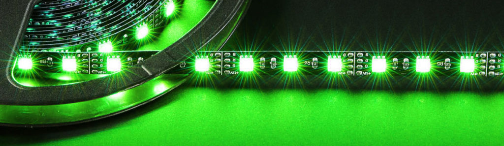
RGB Driver
The board can operate as a full-fledged LED strip driver for 2 independent RGBW modules, fully supported by unicontrol.
Check out the basics of working with unicontrol RGB Driver in the dedicated article.
8. Plain GPIOs
When high-speed communication or specific protocols (like OneWire, Pulse Counter, or Bit-banging) or high-speed analog or touch readings are required, the sensoraya v2 provides direct access to the selected ESP32-S3‘s native GPIO pins.
While these connectors provide 5V to power your sensors, the ESP32-S3 logic is strictly 3.3V. To simplify interfacing with 5V sensors (like certain ultrasonic distance sensors or industrial encoders), we have integrated on-board voltage dividers. If your sensor returns a 5V signal, you can safely step it down by bridging the JP3, JP4, or JP5 solder jumpers. Without the jumpers bridged, the pins act as standard 3.3V I/O. Always verify your sensor’s output voltage and consult the official schematic before bridging these jumpers to ensure correct attenuation.
These are distributed across three dedicated connectors as per the schematic or the following diagram.

9. RTC Module
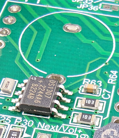
While the DS1307Z+ RTC module is always present by default, the battery socket (BT1) necessary for the module to operate is not included in the raw, partly-fitted board. Ensure that you have the socket with the battery installed if you want the RTC module to function properly.
The on-board socket is optimized for the CR1220 button cell battery.
Under standard operating conditions, the ESP32-S3 synchronizes with NTP servers via the internet to maintain accurate internal clock. However, for critical automation – such as irrigation schedules or security lighting – network reliance can be a point of failure.
To ensure “zero-downtime” timekeeping, the sensoraya features an integrated DS1307Z+ RTC module. This hardware clock retains the current time during power outages or unscheduled reboots, allowing the system to resume scheduled tasks immediately upon power-up, even without a network connection.
This module is connected to the ESP32S3 via pins GPIO39 (SCL) and IO40 (SDA), as indicated in the schematic.

Using the RTC module is not necessary unless the device needs to operate offline or withstand frequent network outages.
Check out the Demo sketches below to try out the RTC functionality.
10. MP3 Module
To support voice notifications, alarms, or music playback, the sensoraya v2 includes a dedicated slot for the DFR0299 (DFPlayer Mini) MP3 module (labeled U10 in the schematic). The module interfaces with the ESP32-S3 via IO41 (RX) and IO42 (TX). This allows for full software control over track selection, volume, and EQ settings. Audio is routed to a dedicated output connector, utilizing the DFPlayer‘s internal amplifier to drive a small 4Ω or 8Ω speaker directly.


Check out the Demo sketches below to try out the MP3 module functionality.
11. Buzzer

The sensoraya v2.1 accommodates an MLT-8530 passive buzzer connected to the IO14 pin of the ESP32S3.

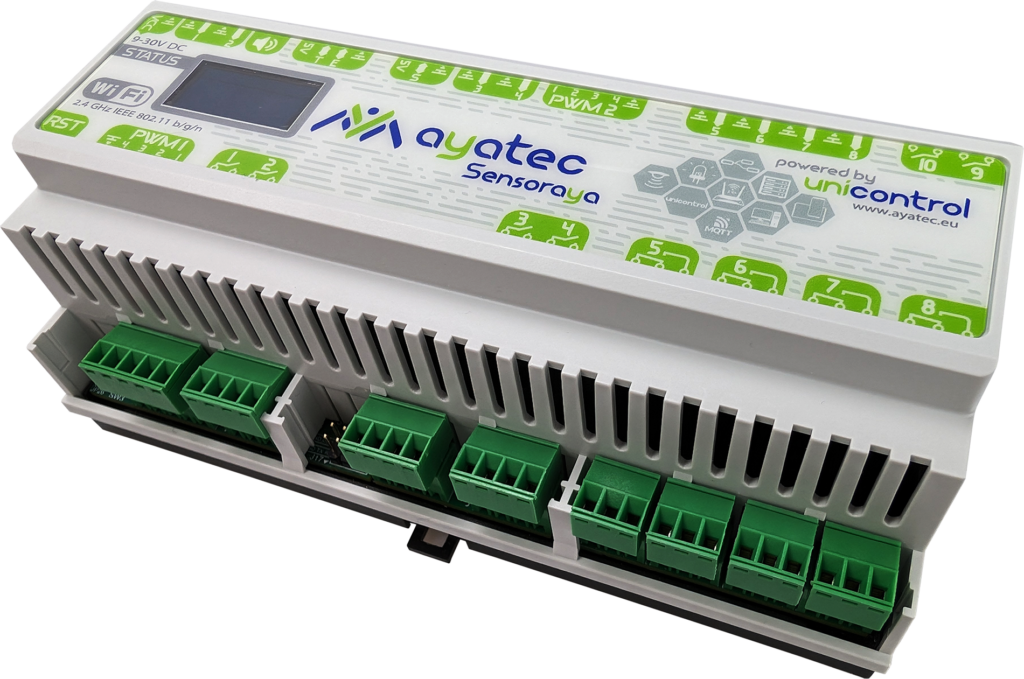
12. PCB casing
To ensure seamless integration into residential and industrial electrical cabinets, the sensoraya PCB is designed to fit standard Hammond DIN rail enclosures. Depending on the size variant of your PCB, the following housings are used:
- Mini (4-Unit): Hammond 1597DIN4GY
- Medium (6-Unit): Hammond 1597DIN6GY
- Maxi (9-Unit): Hammond 1597DIN9GY
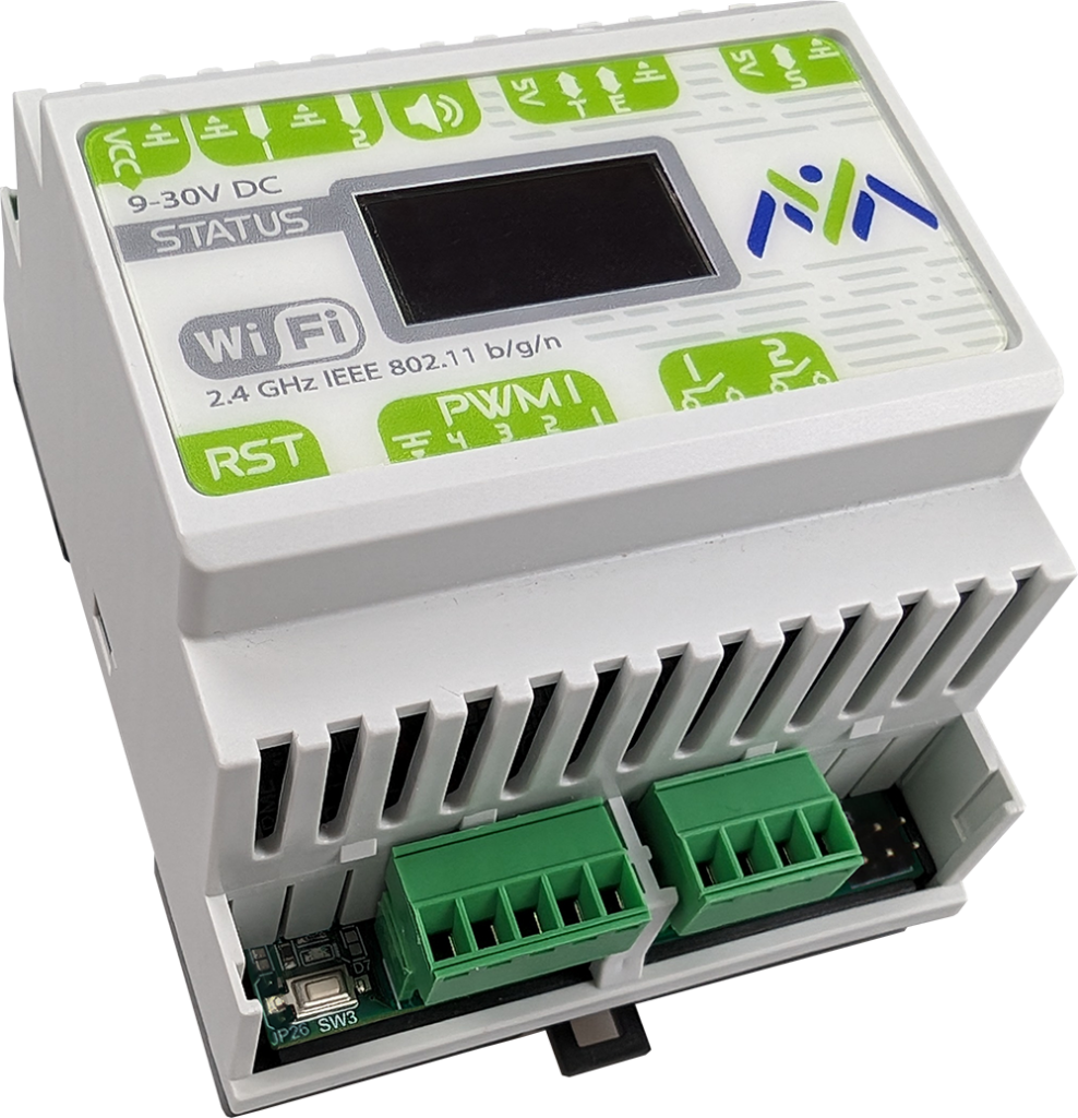
By utilizing these industry-standard enclosures, the resulting modules are fully compliant with standard electrical switchbox requirements. This provides a clean, protected, and professional finish that meets safety expectations for permanent installations.
13. Firmware & Flashing

While the sensoraya v2 is compatible with any ESP32-S3 firmware (such as ESPHome, Tasmota, or MicroPython), it is designed to be the flagship hardware for unicontrol. This native firmware is specifically optimized to handle the board’s shift-register architecture and I/O multiplexing out of the box, maximizing the hardware’s efficiency.
For developers who prefer custom logic, the board functions like any standard ESP32-S3 development module. You can compile and upload your own code using the Arduino IDE, ESP-IDF, or PlatformIO.
The board features a built-in USB-C port connected to an on-board Serial-to-TTL translator (CH340C). This ensures a stable connection for high-speed flashing and serial monitoring across all operating systems without needing external programmers.
GitHub repository
To assist you in developing your own firmware for the sensoraya v2.1, we have prepared a GitHub repository with basic definitions and an extensive set of example sketches for Arduino IDE that demonstrate all of the board’s capabilities.
Get started:
- Install Arduino IDE with the ESP32 boards package
- Install AyatecSensoraya2.x library via the Library Manager
- Connect the board to your PC via a USB-C cable.
- Choose ESP32S3 Dev Module as the board
- Open File → Examples → AyatecSensoraya2.x → 01_Basics → 01_Blink
- Click Upload
14. Additional sources
To continue your journey with us, you may want to check out our online knowledge base. It will help you get on board as quickly as possible, shortening the road to your goals. It ranges from technical details explained in the user guide to real-time, step-by-step demonstrations found in our video tutorials.
- Get inspiration from the Blog posts
- Find answers about unicontrol in the User Guide
- Learn from the Video Tutorials