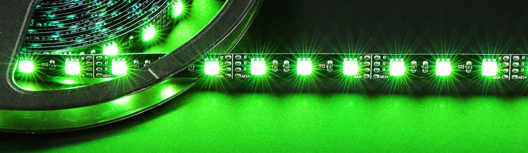
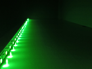
With the release of unicontrol 1.09, one of the most eye-catching features of modern electronics has been implemented: the RGB LED strip driver.
You can now achieve great effects with home-made hardware. Fully integrated with the process control for automation, your LED strips can dynamically respond to buttons, sensors, remote commands, timers, and more!
How it works?
The RGB driver is an independent routine that, as long as at least one color channel appears in the Peripheral menu, displays colors according to four key parameters:
- Mode – The primary parameter that selects the program.
- Color – An auxiliary parameter that defines the rendered color, if applicable (see details below).
- Speed – An auxiliary parameter that defines the animation speed, duration, or delays, if applicable (see details below).
- Brightness – A global modifier that reduces the overall brightness.
Available programs
The unicontrol has a number of predefined programs that can be executed. See the listing below for details:
Rainbow
Loops through all rainbow colors for a predefined duration of a single loop.
Speed: Linearly determines the duration of the whole loop from 5 seconds @100% to 5 minutes @0%.
Color: automatic
Warm Rainbow
Loops through warm colors (red channel always on) for a predefined duration of a single loop.
Speed: Linearly determines the duration of the whole loop from 3 seconds @100% to 3 minutes @0%.
Color: automatic
Cool Rainbow
Loops through cool colors (blue channel always on) for a predefined duration of a single loop.
Speed: Linearly determines the duration of the whole loop from 3 seconds @100% to 3 minutes @0%.
Color: automatic
Thunderstorm 4S
Simulates natural lightning flashes on four independent channels with predetermined pauses between individual lightning clusters.
Speed: Linearly determines the time between lightning clusters from 0-2 seconds @100% to 10-30 seconds @0% (individually for each channel).
Color: not applicable
Sunrise
Simulates a natural sunrise with a color and brightness progression, running for a predetermined time. Ends with full brightness on all channels.
Speed: Non-linearly determines the sunrise duration from 10 seconds @100% to 1 hour @0%.
Color: not applicable
Sunset
Simulates a natural sunset with a color and brightness progression, running for a predetermined time. Ends with all channels turned off.
Speed: Non-linearly determines the sunset duration from 10 seconds @100% to 1 hour @0%.
Color: not applicable
How it is controlled?
Upon defining any of the RGB LED channels in the Peripheral menu, the RGB module’s output starts being rendered and control options are unlocked. Essentially, there are two ways to operate the RGB module, each offering different capabilities and advantages.
A. directly
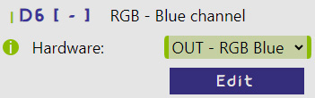
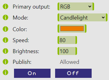
Firstly, you can visit the sub-menu with the RGB module‘s active parameters directly from the Peripheral menu by clicking on Edit button.
There, you can directly access all four primary parameters. Changing them will have an immediate effect on the outputs of the selected pins.
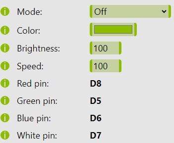
The same effect is achievable by sending MQTT messages for a completely remote access, following the predefined MQTT API. See the example of what it might look like on a smartphone below:
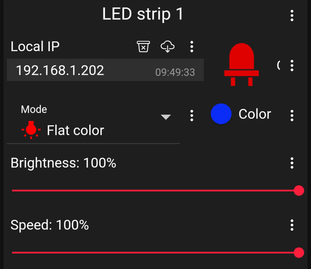
Use this option to immediately achieve the desired program.
B. via process
The RGB module is also fully compatible with the Processes for complete automation capabilities. Each process can include a full set of RGB module parameters, located in the Output section, which is only visible if the RGB is selected as the Primary output.
The RGB output option is only available if at least one of the Red, Green, and Blue channels is active in the Peripheral menu.
Once the underlying process is turned ON, all saved parameters are immediately activated. Turning the process OFF will shut down the program by changing the Mode parameter to Off.
Use this option to automatically apply a certain program in response to a predefined input event. Different inputs may result in different programs being activated.
RGB LED Driver Hardware
Besides the ESP8266, a suitable power supply (typically 12V or 24V), and the RGB LED strip itself, the only missing component to control the strip is the appropriate MOSFET (or a transistor as a last resort) for each color channel.
In this regard, the ESP8266 is a bit more “picky” compared to other similar boards. Unlike many other microcontrollers, such as the Arduino, which outputs 5V, the voltage of the GPIO pins on the most common variants of the ESP8266 (like the WeMos D1 mini, NodeMCU, or the base ESP-12F) is only 3.3V. Unfortunately, this means many commonly used MOSFETs cannot be used with the ESP8266 because they often have a Gate threshold voltage VGS(th) of 4V. This implies that the ESP8266 can never fully open them. Instead, it requires logic-level MOSFETs with up to 2V threshold to be fully opened.
Connect all parts according to the scheme below.
Other MOSFET parameters are also significant. The Voltage rating, V(BR)DSS, should be higher than the strip’s voltage, and the Current rating, ID, should be adequate for the strip’s length. However, these parameters are not as restrictive as the Gate threshold voltage. The IRLZx4N series of MOSFETs is a good choice.
When connecting the Gate of the MOSFET to the ESP8266 GPIO, you might want to use resistors in the range of 100R to 1K for better circuit protection. However, unlike transistors, MOSFETs do not require current limiting.
Many RGB LED strips come with one or even two white channels, as the combination of red, green, and blue does not yield a satisfactory white light. You can utilize these white channels to improve the purity or brightness of the white light.

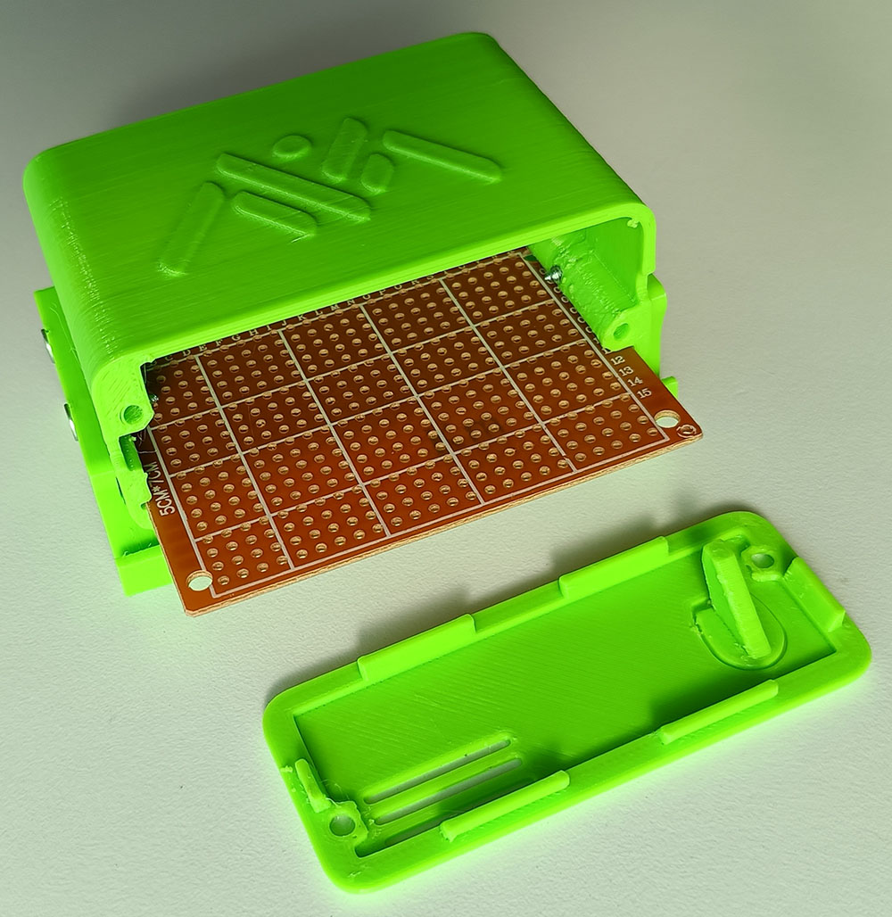
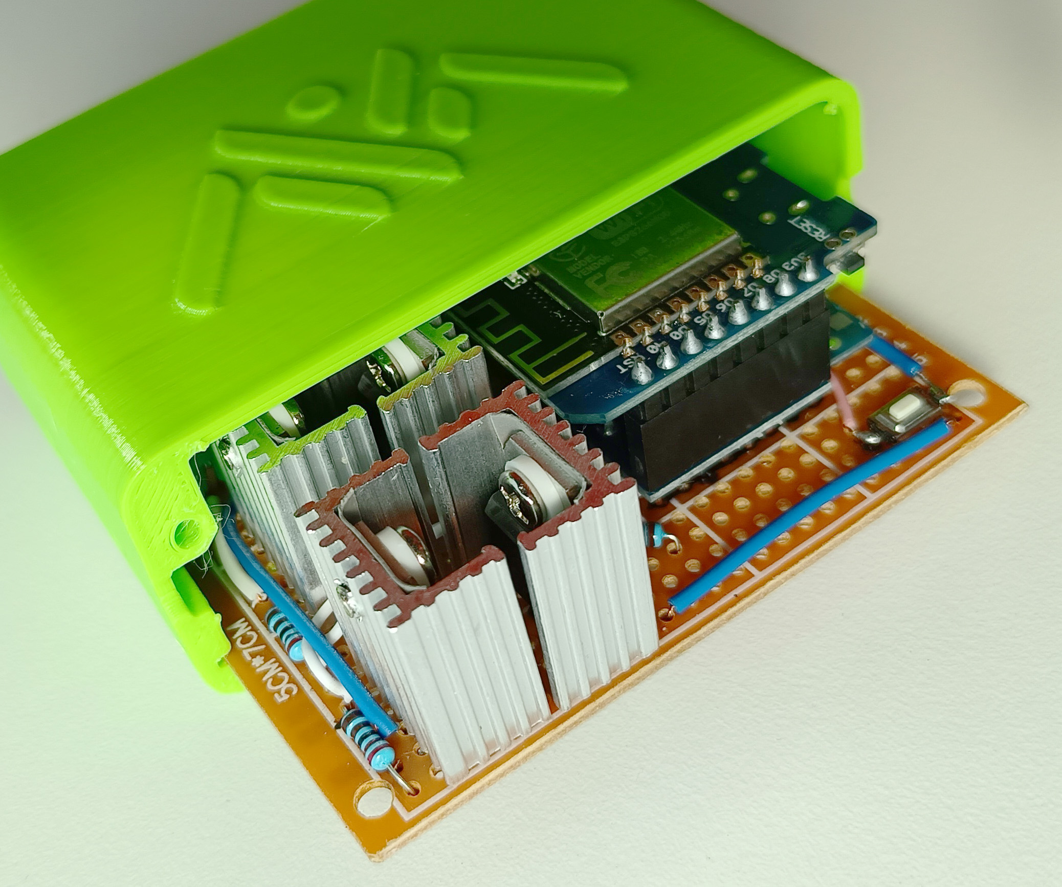
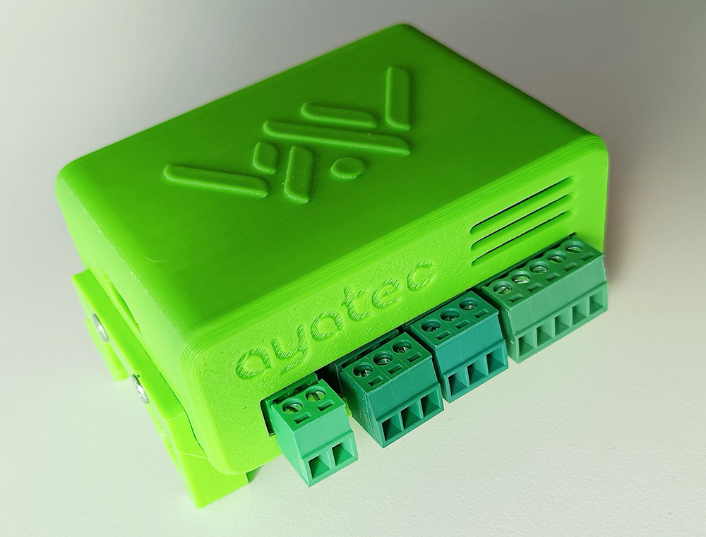
Casing
Unfortunately, despite the numerous ESP8266 relay modules freely available, the choice for MOSFET modules is very limited. Therefore, one of the viable options is to hand-make one for yourself using the provided schematic above, on a 5x7cm universal PCB. To protect your circuits and enhance their aesthetics, you can download an enclosure model from any of the sources listed below and print it for yourself. Check out the results in the included gallery.