1. Introduction
While the ESP8266 microcontroller (with or without unicontrol) still remains to be a powerful choice for any IoT automation project, the bare ESP8266 in any of its forms has a critical lack of I/O options without a supporting PCB. With only 9 digital GPIO pins and 1 analog pin it is underequipped for any sizeable unicontrol project.
To unlock the full potential of the ESP8266, we have developed our own ayatec sensoraya PCB. It expands the input and output capabilities of this microcontroller, making it a formidable choice for any smart application.
Both our software and hardware are highly customizable, maximizing their synergy and expanding the range of possibilities achievable with them. Together, they can become anything from compact, simple applications to highly specialized automation systems.
2. PCB Changes and Uses
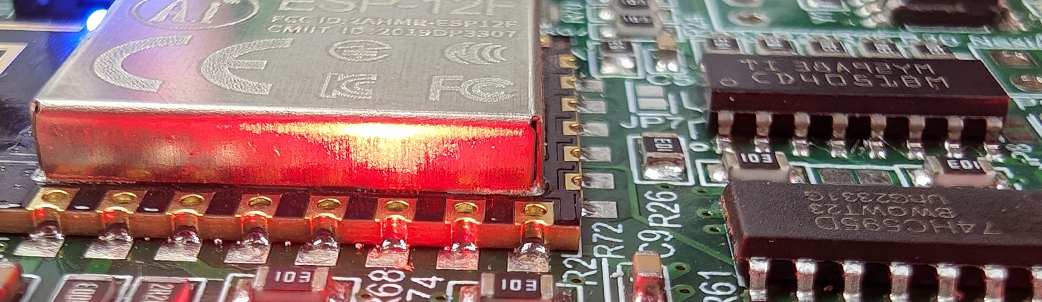
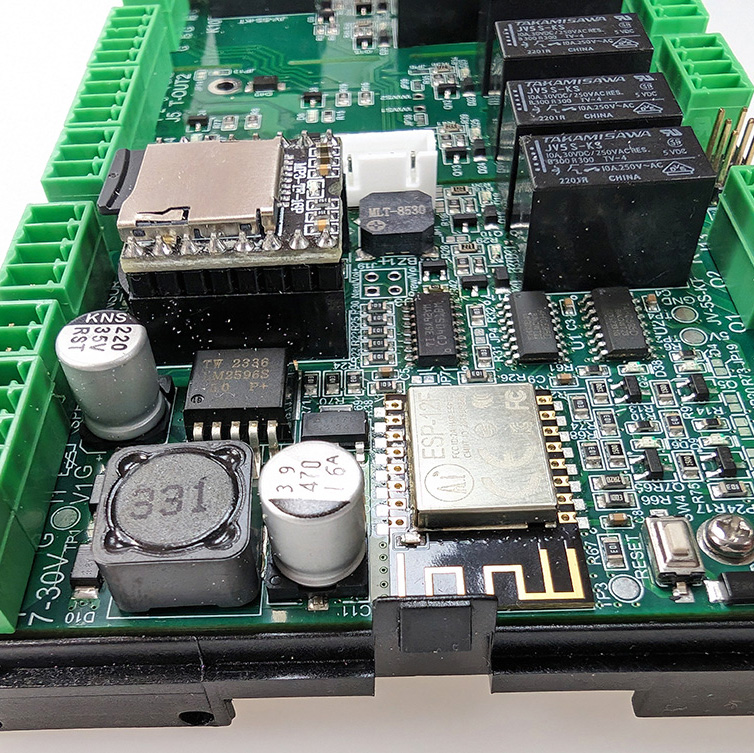
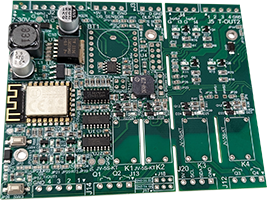
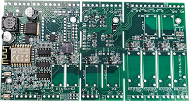
The presented version 1.4 of the sensoraya PCB, compared to its predecessors, has a built-in ESP-12F and a powerful 7-30V -> 5V power adapter, replacing the modular sockets for the D1 mini boards. It also features upgraded MOSFETs and has an optimized layout with added connectors and solder-jumpers for better variability. While the original Hammond casing was retained, the final design has been revamped. The upgraded board has become superior to any other ESP8266-based hardware available in the market, ready to control a wide variety of devices and components, whether in home, small business, or industrial automation. You may get inspiration from the following, by far not exhaustive list:
- an autonomous, or remotely controlled smart relay box,
- an autonomous irrigation system,
- an aquarium or a swimming pool controller,
- a sauna or spa control including attractions,
- an indoor or outdoor LED lighting control,
- a remote gate control,
- a tank water level monitoring system with autofill,
- an autonomous thermostat or A/C,
- a temperature or air quality monitor,
- and a lot more!
3. PCB Sizes
The I/O diagrams and descriptions provided here relate to the maximum configuration of the sensoraya PCB. However, the board’s core segment A is designed to be fully autonomous even with the segments B and/or C removed, effectively constituting 3 different size variants for this PCB only differing in the number of I/O ports.
For the comprehensive listing of hardware capabilities of all the size variants you may check the following overview:

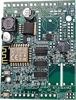
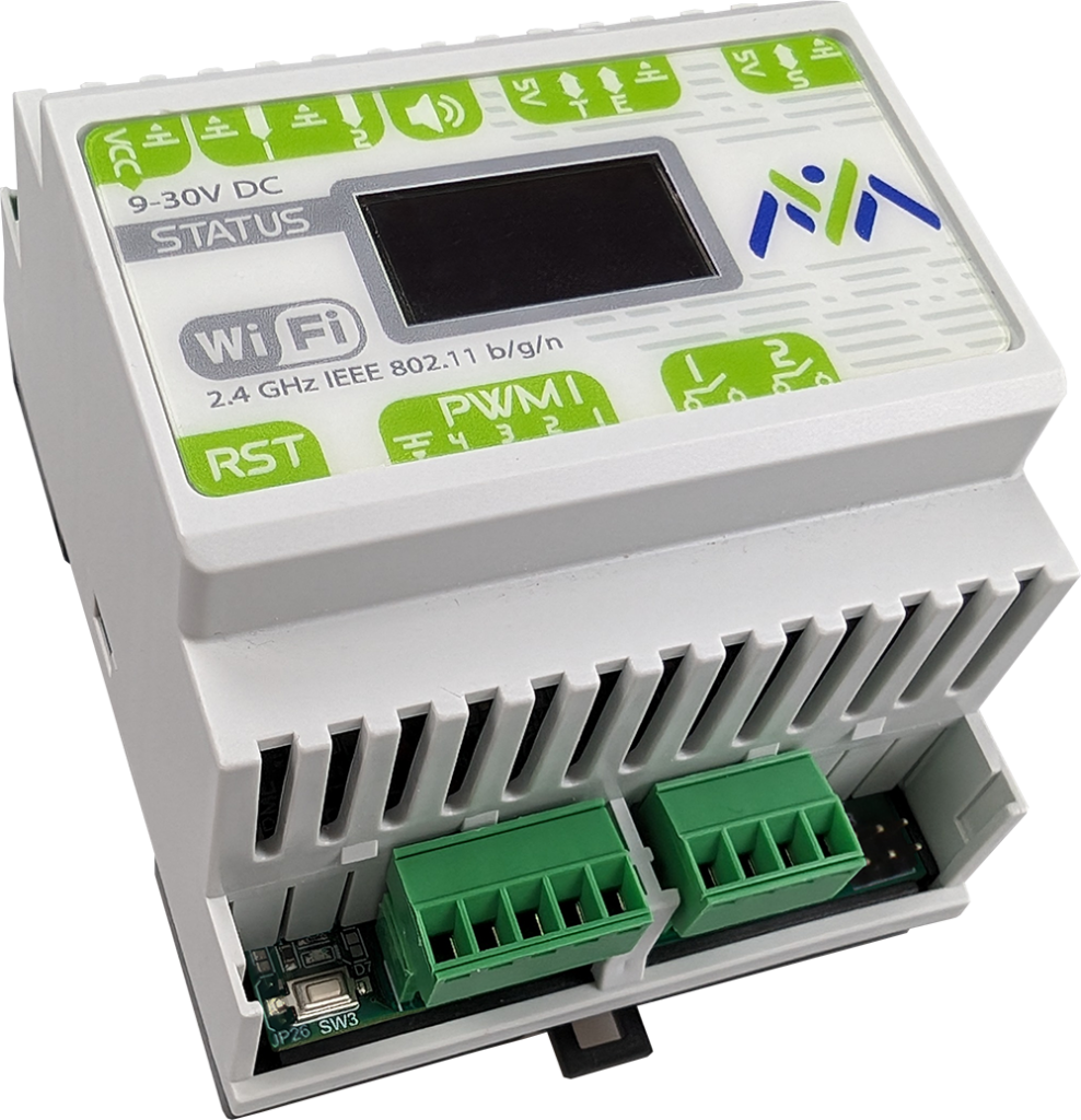
Mini variant
(4-Module)

The board’s bare core contains the ESP8266 microcontroller with the 7-30V VIN adapter and:
- 2 relays
- 2 analog inputs
- 4 MOSFETs
- 3 direct GPIO digital inputs
- I2C dedicated connector
- MP3 module
Mini variant is the smallest option (only 7 cm wide), suitable for the most basic applications requiring no more than 2 relays and a small number of inputs or digital outputs. It is often unnecessary to use the integrated Shift Register with this variant.
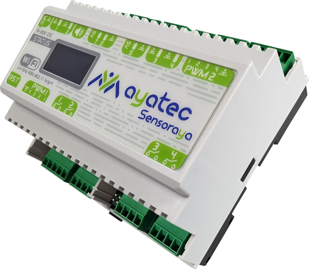
Medium variant
(6-Module)

Contains all options from the Mini variant with the addition of:
- 2 relays
- 2 analog inputs
- 4 MOSFETs
- I2C or custom connector
Medium variant is the medium option (10,5 cm wide), adding some options for both inputs and output and representing a middle ground sufficient for most mid-sized applications.
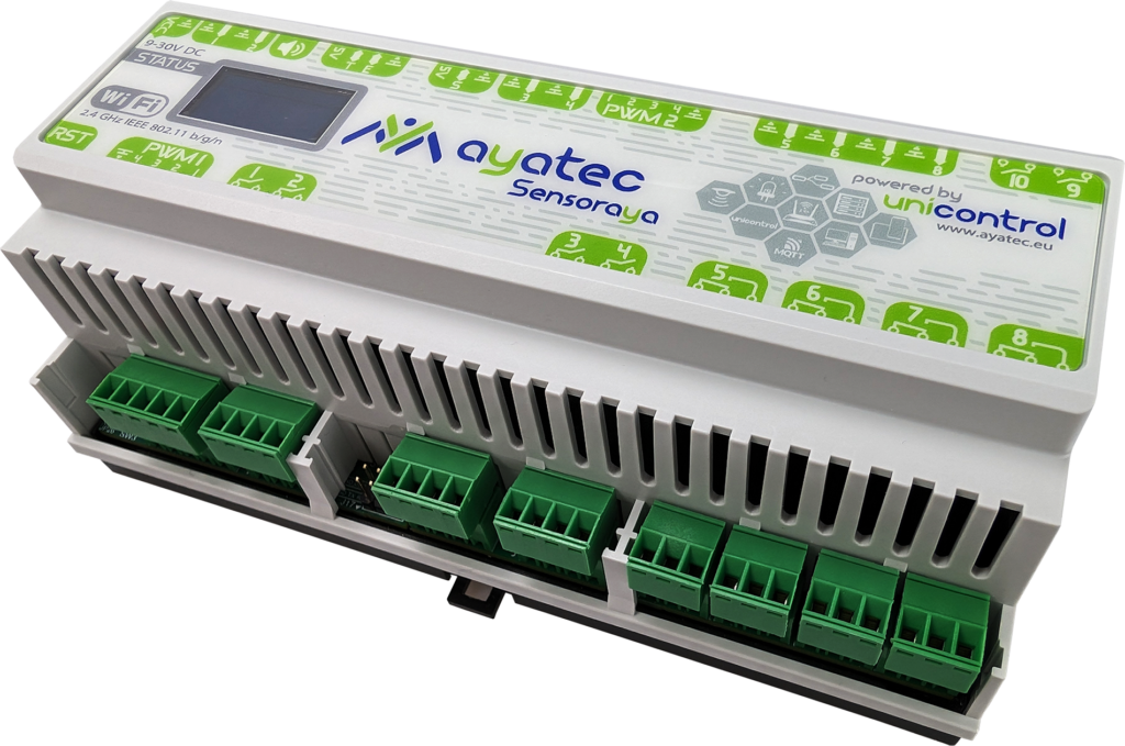
Maxi variant
(9-Module)

Contains all options from the Medium variant with the addition of:
- 6 relays
- 4 analog inputs
Maxi variant is the most powerful and largest option (16 cm wide), offering all the above described hardware options. This variant is suitable for the most demanding projects.
4. PCB Variants
The sensoraya PCB offers a wide range of I/O options. As not all options can be utilized simultaneously, the final configuration and resulting functionality depend on bridging (or not bridging) the 39 on-board solder bridge jumpers (JP1 – JP39 in the schematic).
For instance, according to the schematic, the D7 pin (GPIO13) of the ESP8266 can be used to help operate Relays via the Shift Register (default), function as a General I/O via the connector J21, or control a Power MOSFET on connector J14. However, it cannot perform all these functions simultaneously.
Always refer to the schematic to ensure correct jumper connections and to avoid potential malfunctions or damage.
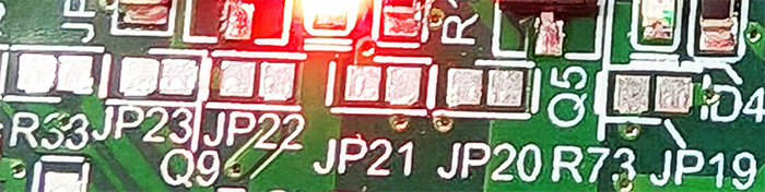
By default, all jumpers are open and need to be bridged by adding a drop of tin if they are intended to be part of a circuit. The numerous combinations and resulting variants enabled by these jumpers allow users to customize their setup according to their specific needs.
5. PCB I/O description
The ayatec sensoraya PCB expands the ESP8266‘s original 9 digital and 1 analog pins to up to:
- 10 relays (4x 8A @ 250V AC (Changeover) + 6x 5A @ 250V AC)
- 8 analog inputs (0-3.3V)
- 8 power MOSFETs (max 2.5A @ 30V DC without cooling)
- I2C dedicated connector (primarily intended for a 0.96 128X64 I2C Display)
- 3 direct GPIO digital inputs (primarily intended for digital peripherals like DS18B20, 1838 IR, HC-SR04, or similar)
- RTC module
- MP3 module
- Buzzer

The board requires a power supply of 7-30V DC via a dedicated connector in the upper-left corner of the board. Make sure that your power supply is capable of providing at least 10W.
The listing above represents the maximum configuration for each separate type of I/O with many configuration options. However, it is impossible to accommodate all I/O port combinations listed above simultaneously as they are often sharing the same GPIOs as per the schematic.
The final functionality of the hardware is determined by manually bridging (or not bridging) individual solder jumpers JP1 – JP39, connecting respective components to various GPIO pins. Placement of these jumpers also defines limitations of various hardware combination.
Any existing combination, however, can be reflected in the unicontrol firmware, for example in the input and/or output peripherals.
For more detailed information on each type of I/O, please continue to the following sections.
Schematic
Navigate to the following schematic for the sensoraya PCB v1.4 technical reference.
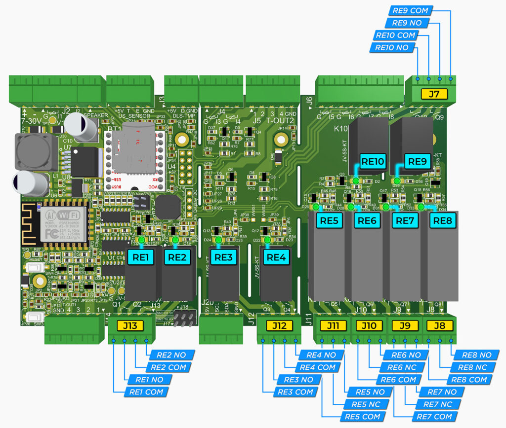
6. Relay Outputs
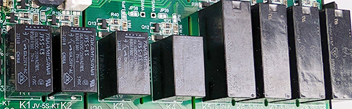
As the most basic output, the sensoraya PCB features up to 10 medium-load power relays of the following two types:
- 2-terminal relay with maximum load of 5A @ 230V (up to 6 units in total, 2 units located on each of the segments A, B, and C)
- 3-terminal changeover relay with maximum load of 8A @ 230V (up to 4 units in total, all located on segment C)
The on-board relays can only be accessed in combination with the board’s built-in Shift Register and its output pins RE1 – RE10. Following 4 relays are an exception as they are also accessible via on-board solder-jumpers as per the schematic:
RE1– can be attached to D0 (GPIO16) via a solder-jumperRE2– can be attached to D3 (GPIO0) or D8 (GPIO15) via solder-jumpersRE3– can be attached to D1 (GPIO5) via a solder-jumperRE4– can be attached to D2 (GPIO4) via a solder-jumper
Each relay has a dedicated indicator LED showing the current output state of the respective relay.
The last pin of the two Shift Registers is used as a System LED used all the time when the Shift register is in use and is otherwise inaccessible by the user.
Please note that using the Shift Register blocks the D5, D7, and D8 pins, rendering them unusable for other purposes.
Check out the Demo firmware below to try out the Shift Register functionality.
Connectors J7 – J13 are dedicated to the power relays. Two-terminal relays share 4-pin connectors in pairs, while each three-terminal relay has its own 3-pin connector.
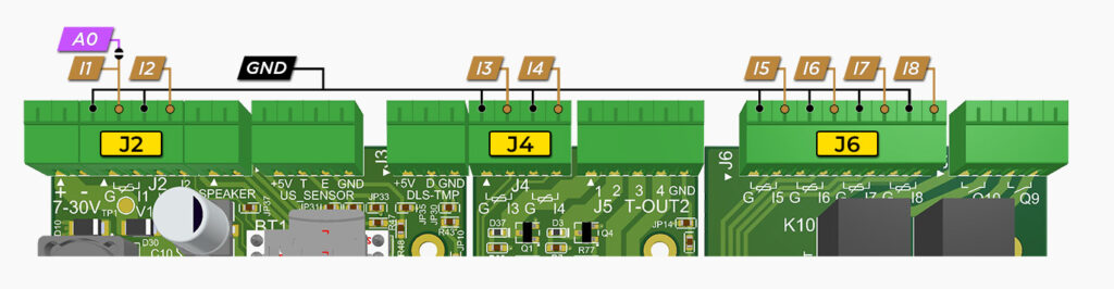
7. Analog Inputs
As the most common analog and logical inputs, the sensoraya PCB carries up to 8 analog pins I1 – I8, compared to a single native A0 pin on ESP8266.
The analog inputs can only be accessed via dedicated connectors J2, J4, and J6 (the reserve connector J16 can also serve to access inputs I5 – I8). These are controlled by the board’s built-in Shift Register and Analog Multiplexer. Each of these inputs has a built-in 10k pull-up resistor. This allows for the direct use of various analog sensors with the board, without the need for additional wiring.
Please note that using the Shift Register blocks the D5, D7, and D8 pins, rendering them unusable for other purposes.
Check out the Demo firmware below to try out the Shift Register & Analog Multiplexer functionalities.
As per the schematic and system defaults, the I8 input is initially connected to the System button but can also function as a common analog input.
Please note that I1 – I8 inputs are slow, only evaluated up to 12 times per second. It is therefore not recommended to use them for inputs with narrow impulses, which can be easily overlooked by the firmware.
8. Power MOSFET Outputs
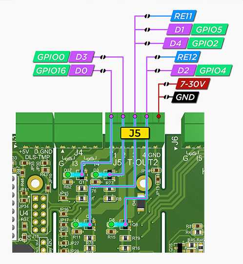
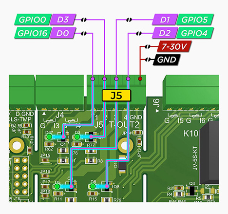
The board accommodates up to 8 independent AO3400A power MOSFETs capable of functioning either as a PWM or as a simple digital output. These can be accessed via the 5-pin connectors J14 and J5, located on segments A and B, respectively.
In the left-most position of each connector, there is a combined VIN/GND pin. The selection between VIN and GND determines the operation mode of the respective connector:
- If the VIN jumper is connected, the pin will supply the board’s VIN, acting as the power supply for connected components such as an LED strip or a contactor. In this scenario the board’s power supply needs to have sufficient rating to be able to power the board and the connected components simultaneously.
- If the GND jumper is connected, the pin can be utilized in an open collector configuration to link the external power supply’s GND_ext. Meanwhile, VIN_ext from the external power supply will provide power to connected components such as an LED strip or a contactor. In this setup, the power supply for the MOSFET circuits is completely independent from the board’s power supply and may even operate at different voltages. In this scenario the PCB has its own independent power supply and will not be affected by the components connected to the MOSFETs.

Under no circumstances should the combined VIN/GND pin have both VIN and GND jumpers bridged simultaneously. Failing to adhere to this may result in permanent damage to the PCB and connected electrical components.
Each of the remaining 4 pins on either of the connectors represents one individual MOSFET. To maximize the potential for hardware combinations and possible applications, each individual MOSFET has very different options for connecting it to the boards Peripherals.
J5
(left to right):
- D0 (GPIO 16, connected by default)
- D3 (GPIO 0, connected by default)
- D4 (GPIO 2, connected by default), or, alternatively, D1 (GPIO 5), or RE11
- D2 (GPIO 4), or RE12
- VIN (connected by default), or, alternatively, GND
Each MOSFET has a dedicated indicator LED showing the current output state of the respective MOSFET.
The RE11 and RE12 I/O peripherals can only be used in combination with the board’s built-in Shift Register and its output pins as per the schematic.
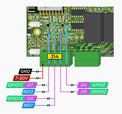
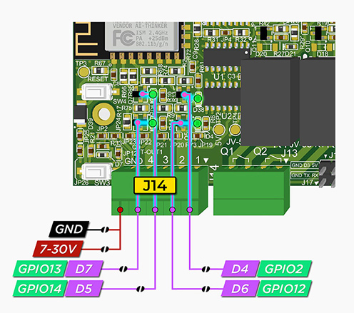
J14
(right to left):
- D4 (GPIO 2)
- D6 (GPIO 12)
- RE11 (connected by default), or, alternatively, D5 (GPIO 14)
- RE12 (connected by default), or, alternatively, D7 (GPIO 13)
- VIN (connected by default), or, alternatively, GND
RGB Driver
In the most extreme case, the board can operate as a full-fledged LED strip driver for 2 independent RGBW channels, which is fully supported by unicontrol.
Ensure that only the relevant jumpers are bridged according to the diagram or scheme to prevent any unintended behavior.
Check out the basics of working with unicontrol RGB Driver in the dedicated article.
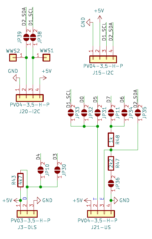
9. Direct Access to ESP8266 GPIO
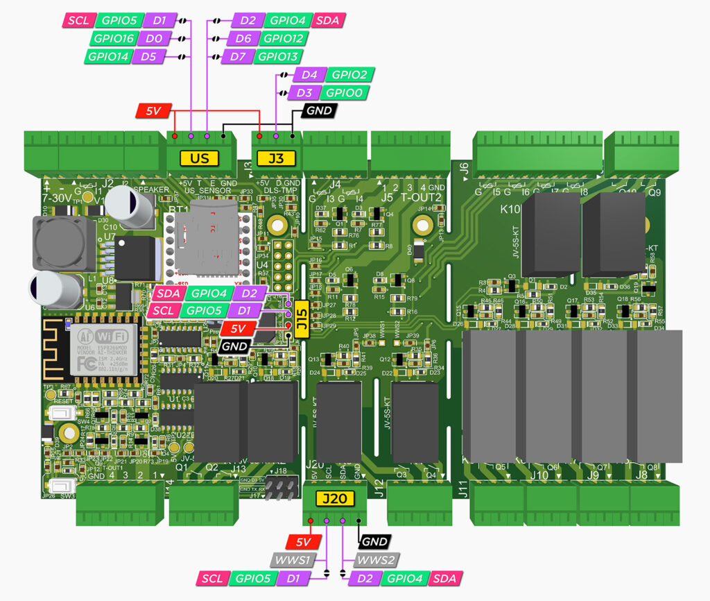
In cases where neither of the I/O options above suffice, the sensoraya PCB offers several possibilities to directly access the ESP8266‘s GPIO pins without any intermediary hardware, as per the schematic. For this purpose, the board possesses the following four connectors with a direct connection to the ESP8266’s GPIO pins:
- US (also labeled as J21): Carries two contacts leading directly to the ESP-12F, with multiple combinations of GPIOs they can lead to, determined by the jumpers. The connector is intended for use with standard 4-pin devices (
VCC,GND, and 2 data pins) like SR04 ultrasound sensors, ENS160 CO2 sensor, and many more.GPIO5(D1) andGPIO4(D2) are connected by default, but this configuration can be easily changed. - J3: Carries one pulled-up contact directly to the ESP-12F, with two options:
GPIO2(D4) orGPIO0(D3). The connector is intended for use with standard 3-pin devices (VCC,GND, and a single data pin) like DS18B20 thermometers, DHT11/DHT22, 1838 IR Receiver, Pulse sensors, or any other. - J20: Carries two data pins. This connector serves as a situational reserve. It can either function as an additional I2C outlet or have its data pins manually hardwired to any supporting hardware added by the user via the universal
WWS1andWWS2holes. - J15: The primary I2C bus, intended as an I2C Display connector by default.
Here is a summary of all wiring options:
- US, position 2 (T): Choice between
GPIO5(D1, default),GPIO14(D5), andGPIO16(D0). - US, position 3 (E): Choice between
GPIO4(D2, default),GPIO12(D6), andGPIO13(D7). Optional pull-down resistor. - J3, position 2 (D): Choice between
GPIO2(D4, default) andGPIO0(D3). Permanent pull-up resistor. - J20, position 2 (SDA): Choice between
WWS2(universal, permanently connected) andGPIO4(D2). - J20, position 3 (SCL): Choice between
WWS1(universal – permanent) andGPIO5(D1). - J15, position 3 (SCL):
GPIO5(D1) – permanent - J15, position 4 (SDA):
GPIO4(D2) – permanent
Connector J18, GPIO0 (D3) is intentionally omitted from the listings above, as it is exclusively intended for flashing purposes only.
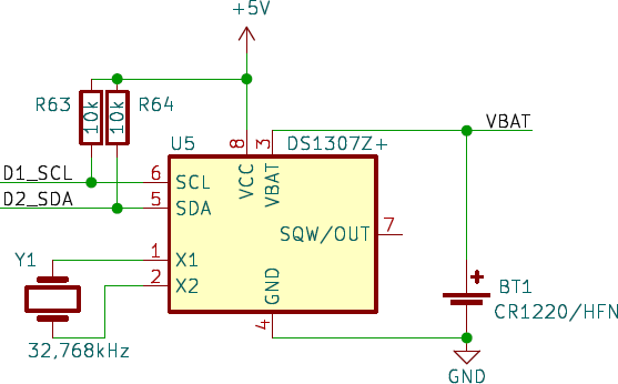
10. RTC Module
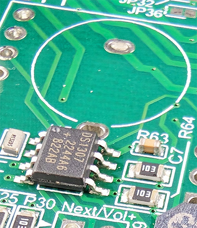
While the DS1307Z+ RTC module is always present by default, the battery socket (BT1) necessary for the module to operate is not included in the raw, partly-fitted board provided, for example, in the DIY kits. Ensure that you have the socket with the battery installed if you want the RTC module to function properly.
Under normal circumstances, the ESP8266 is permanently connected to the local Wi-Fi network with internet access, drawing the current time from there. However, this may not always be the case. To ensure reliable time control even in instances of missing internet connection, the PCB has a built-in DS1307Z+ RTC module, which retains the real-time clock during unscheduled reboots or power outages. This module is connected to the ESP8266 via its native I2C pins GPIO5 (D1, SCL) and GPIO4 (D2, SDA), as indicated in the schematic.
Using the RTC module is not necessary unless the device needs to operate offline or withstand frequent Wi-Fi or internet outages.
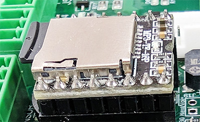
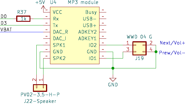
11. MP3 Module
The board is adapted to accommodate the DFR0299 DFPlayer mini MP3 module (labeled U4 in the schematic). It is connected to the ESP8266 via D0 (GPIO16) and D3 (GPIO0) pins and has a dedicated connector for the audio output. The board also features reserve holes for a WWD 2×2 connector (J19) that can be used to control the module directly if needed.
Check out the Demo firmware below to try out the MP3 module functionality.

12. Buzzer

The sensoraya PCB accommodates an MLT-8530 passive buzzer connected via jumper to the D6 (GPIO12) pin of the ESP8266.

Use as an immediate feedback to the user, for example in case of some non-standard or adverse situation, preventing potential damage.
13. PCB casing
The original sensoraya control modules come in the standard Hammond DIN rail enclosures (1597DIN4GY, 1597DIN4GY, or 1597DIN4GY), depending on the size variant. The resulting modules are therefore fully compatible and compliant with all electrical and safety standards, casing-wise, and can fit into any standard electrical switch box.
14. Firmware & Flashing

The native firmware designed for use with sensoraya PCB is unicontrol. Although the board can support any ESP8266-compatible firmware, this combination is optimized to work together, maximizing each other’s capabilities.
However, the board can be programmed with either downloaded or custom-made firmware, similar to any other ESP8266-based board. This can be accomplished using standard software such as the Arduino IDE or ESP-IDF. If you have received a blank board or the existing firmware does not meet your needs, follow the steps below to upload new firmware to the board.
Flashing
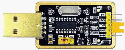
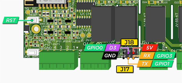
To upload the firmware to sensoraya, the user needs to connect it to a computer via a UART-USB converter. The board features dedicated connectors labeled J17 and J18, located in the bottom-right corner of segment A, making it easy to access all necessary GPIO pins.
For this purpose, we recommend using a CH340 module with a 5V pin. This will ensure that the on-board ESP8266 receives power from the converter itself, eliminating the need for an additional power cable during flashing.
Now, follow the steps listed below:
- Connect the UART-USB converter to the PCB by matching the following pins:
TX -> TX,RX -> RX,GND -> GND, and5V -> 5V.
The pin layout of the UART-USB converter may vary slightly depending on your specific model, so refer to its individual specifications for guidance. For more detailed instructions on connecting the UART-USB converter to the ESP8266 module, please refer to our Serial line tutorial.
- Connect the D3 (
GPIO0) pin toGNDusing a jumper-wire. While these two are connected, press theRSTbutton. This action will boot the ESP8266 in flashing mode. Afterward, disconnect the D3 (GPIO0) pin fromGND. (Do not reset the board yet.) - The board is now ready to be flashed. Your computer should recognize the COM port of the UART-USB converter, and any compatible flasher will be able to upload the firmware. Use any flash procedure that suits you:
- click “Upload” in Arduino IDE, or
- click “Install” in our web flasher, or
- click “Flash” in the Firmware Programmer, or
- any other similar procedure.
- Once the process is complete, you may press the
RSTbutton to boot the newly uploaded firmware. Ensure that the D3 (GPIO0) pin is disconnected fromGNDat this point.
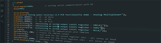
Demo firmware
To assist you in developing your own firmware for the sensoraya PCB, we have published a set of example codes for Arduino IDE that demonstrate selected functionalities:
15. Further education
To continue your journey with us, you may want to check out our online knowledge base. It will help you get on board as quickly as possible, shortening the road to your goals. It ranges from technical details explained in the user guide to real-time, step-by-step demonstrations found in our video tutorials.
- Get inspiration from the Blog posts
- Find answers about unicontrol in the User Guide
- Learn from the Video Tutorials
- Ask in the Discussion Forum